Posterior cervical fusion system and techniques

a cervical fusion and posterior cervical technology, applied in the field of posterior cervical fusion surgery, can solve the problem of reducing the likelihood of inaccurate placement of screws in the superior/inferior trajectory, and achieve the effect of reducing the likelihood of inaccurate placement of screws

Active Publication Date: 2012-08-23
NUVASIVE
View PDF28 Cites 49 Cited by
  • Summary
  • Abstract
  • Description
  • Claims
  • Application Information

AI Technical Summary

Benefits of technology

[0006]According to one embodiment, a screw insertion technique includes inserting a screw system during open surgery or while using minimally invasive techniques. The screw insertion technique may also be used in a purely percutaneous fashion or through a tubular or expandable minimally invasive retractor system. The technique uses the facet joint to guide the screws into position. A spatula or “facet sled” is inserted within the facet joint under radiographic guidance. Once the sled is in place, the screws can be guided along the sled device enabling the placement of the screws based on the patient's natural anatomy. By placing the “sled” as a guide in the facet joint, the joint itself provides the trajectory for the screws to then be inserted. The screws will therefore have the appropriate cranial-caudal trajectory to improve accuracy for screw placement. The screws can be attached to towers similar to those used in lumbar systems to allow for insertion of the rod.
[0008]The present invention has distinct advantages over prior art posterior screw systems. First, the invention provides a technique and assembly for placing screws in the posterior cervical spine. Second, the sled provides an accurate trajectory along the facet joint, which automatically provides the appropriate trajectory for each screw and reduces the likelihood of inaccurately placed screws in the superior / inferior trajectory.

Problems solved by technology

Second, the sled provides an accurate trajectory along the facet joint, which automatically provides the appropriate trajectory for each screw and reduces the likelihood of inaccurately placed screws in the superior / inferior trajectory.

Method used


Image

  • Posterior cervical fusion system and techniques
  • Posterior cervical fusion system and techniques
  • Posterior cervical fusion system and techniques

Examples


first embodiment

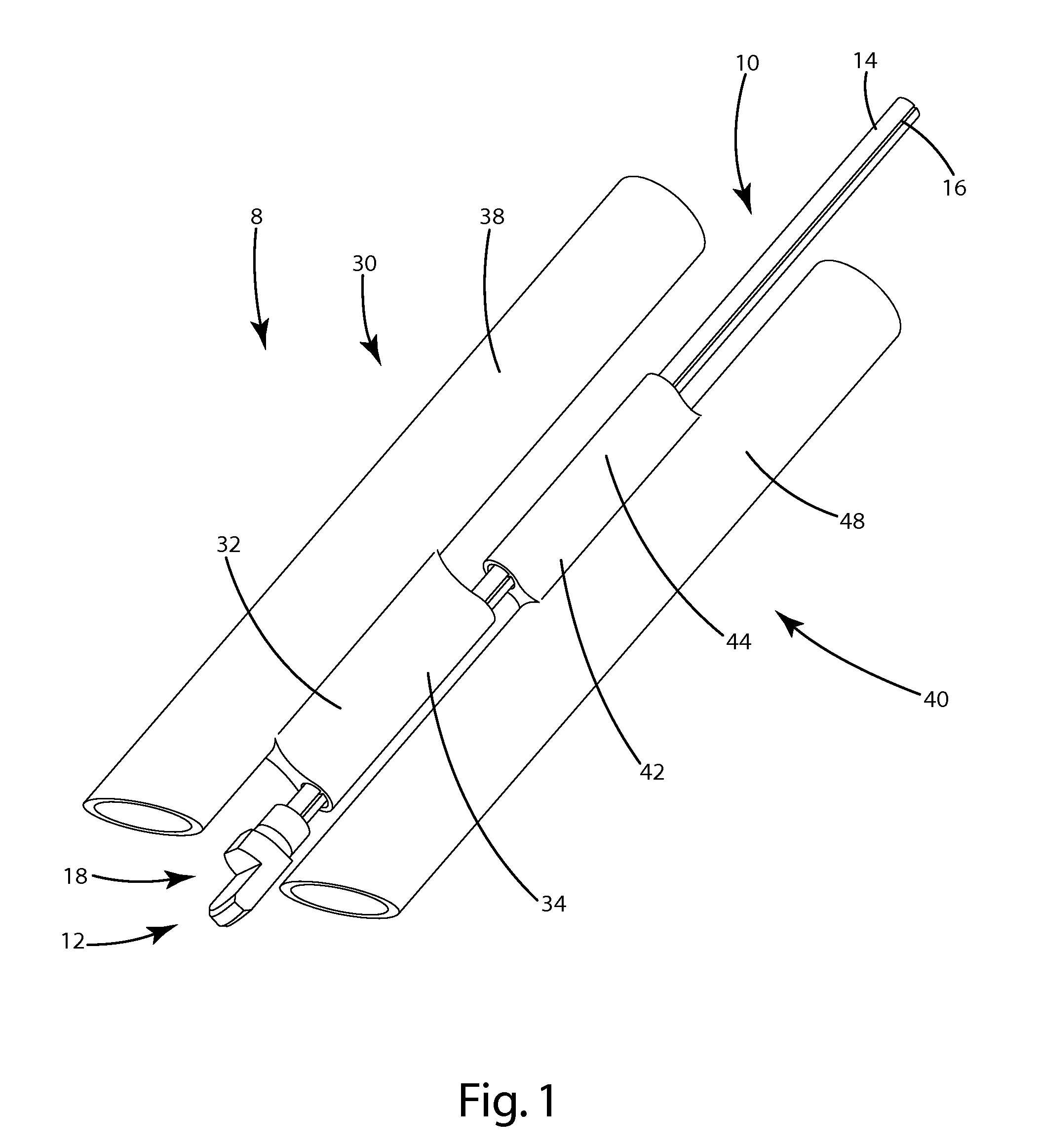
[0025]Two current embodiments are disclosed in this application. In the first embodiment, shown in FIG. 1, the assembly 8 includes a superior cylindrical extension 30, positioned substantially above the handle 14, and an inferior cylindrical extension 40, positioned substantially below the handle 14. As used in this context, the terms “above” and “below” are in reference to the handle 14 when the end 12 is inserted into the facet joint 50 between the first vertebra 52 and the second vertebra 54 and the patient is upright. In other words, “above” indicates a direction from the handle generally upward toward a patient's head, but away from the patient's body and “below” indicates a direction from the handle generally downward away from a patient's head but towards the patient's body.

[0026]As shown in FIG. 1, the superior cylindrical extension 30 and inferior cylindrical extension 40 are slidably coupled to the facet sled handle 14. The cylindrical extensions 30, 40 include elongated r...

second embodiment

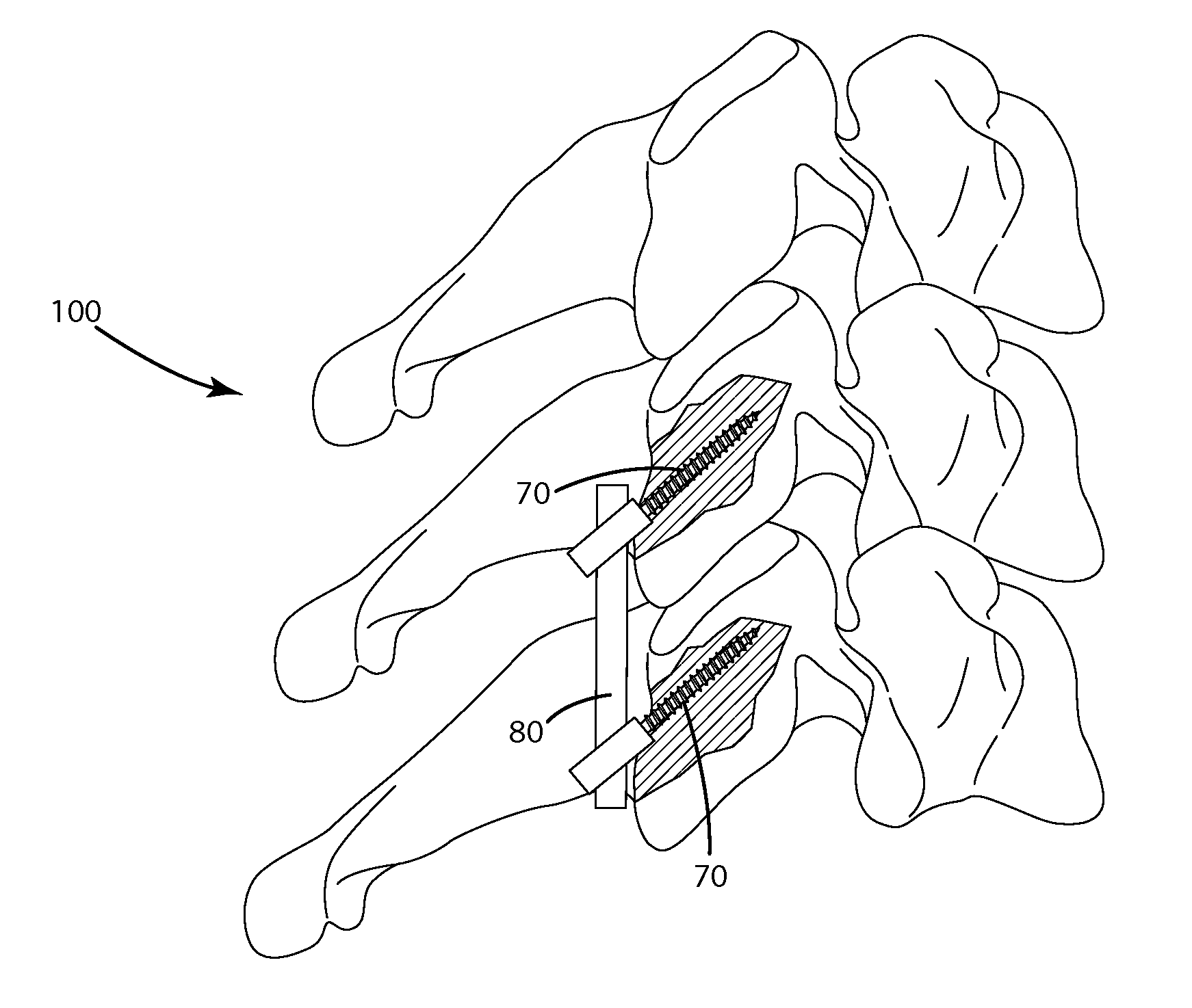
[0028]In the second embodiment, shown in FIGS. 13-14, the surgical instruments slidably engage the facet handle 14. In this embodiment, the assembly 8 may include at least one screw tower or extension 72, which is adapted to support a screw 70 for insertion into the patient's spine 100. Extending from the screw tower 72 is at least one guide member 32″, 42″, which engages and slides along the handle 14. The insertion of the facet sled 10 into the facet joint 50 allows the handle 14 of the facet sled to establish the proper trajectory along which the screw towers 72 and other surgical instruments can travel to properly insert the screws 70 into the patient's spine 100.

I. Structure

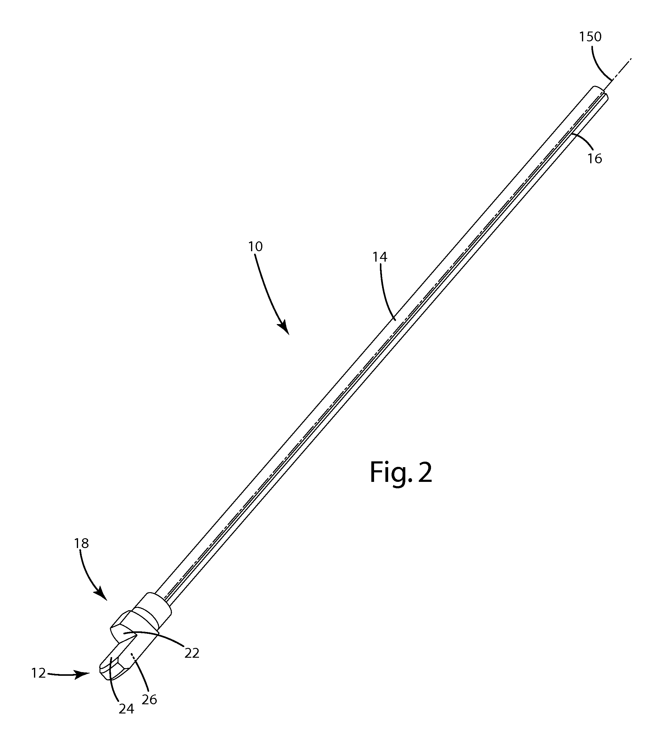
[0029]The facet sled 10 may be formed in any shape and size suitable to allow the sled 10 to be inserted into the facet joint 50 of the patient. As shown in FIG. 2, the end 12 of the facet sled is generally flat and is sized to slide between the vertebrae 52, 54 of the patient. The end 12 may optionally be t...


PUM


Abstract

A posterior cervical fusion surgery assembly and method. The assembly includes a sled adapted to be positioned in a facet joint and two receivers slidably mounted on the sled. The receivers are adapted to support surgical instruments such as a drill, a tap, and a screw. The sled assists in orienting the instruments at a desired angle with respect to the spine.

Description

BACKGROUND OF THE INVENTION[0001]The present invention relates to posterior cervical fusion instrumentation and to posterior cervical fusion surgery.[0002]The facet joint or “zygapophysial” joint is a synovial joint between the superior articular process of one vertebra and the inferior articular process of the vertebra directly above it. There are two facet joints in each spinal motion segment (right and left). The biomechanical function of each pair of facet joints is to guide and limit movement of the spinal motion segment. These functions can be disrupted by degeneration, dislocation, fracture, injury, instability from trauma, osteoarthritis, and surgery.[0003]Posterior cervical fusion surgery has become a common procedure for the treatment of degenerative disease of the cervical spine. In such surgery, fusion hardware, including plates and / or screws, are installed along the cervical spine to stabilize the bones, thereby facilitating fusion of the neck. Posterior cervical fusion...

Claims


Application Information

Patent Timeline
Patent Type & Authority Applications(United States)
IPC IPC(8): A61B17/70A61B17/88
CPCA61B17/1671A61B17/7064A61B17/1757
Inventor CANNESTRA, ANDREW F.
Owner NUVASIVE
Why Eureka
Try Eureka