
Gas turbine intercooler with tri-lateral flash cycle

Inactive Publication Date: 2012-08-30
GENERAL ELECTRIC CO
View PDF0 Cites 29 Cited by
  • Summary
  • Abstract
  • Description
  • Claims
  • Application Information

AI Technical Summary

Benefits of technology

[0010]an expansion machine configured to expand the heated organic fluid via a Tri-Lat

Problems solved by technology

Gas turbines alone have a limited efficiency and a significant amount of useful energy is wasted as hot exhaust gas that is discharged to the ambient.
An intercooler facilitates increasing the efficiency of the engine; however, the heat rejected by the intercooler is not utilized by the gas turbine engine, and the intercooler heat from an intercooled gas turbine or compressor is usually wasted.
Discharging the heat at low temperature requires rather large heat exchangers and fans.
However, since this is low-grade heat, available only at temperatures below that of the compressor discharge air, using this heat in an efficient way to generate electricity is challenging.
A conventional ORC (similar to a steam cycle) has a disadvantage for this application, since a large fraction of the heat is extracted at the boiling temperature, leading to a pinch-point problem that limits the amount of heat and the exit air temperature.

Method used


Image

  • Gas turbine intercooler with tri-lateral flash cycle
  • Gas turbine intercooler with tri-lateral flash cycle
  • Gas turbine intercooler with tri-lateral flash cycle

Examples


Embodiment Construction

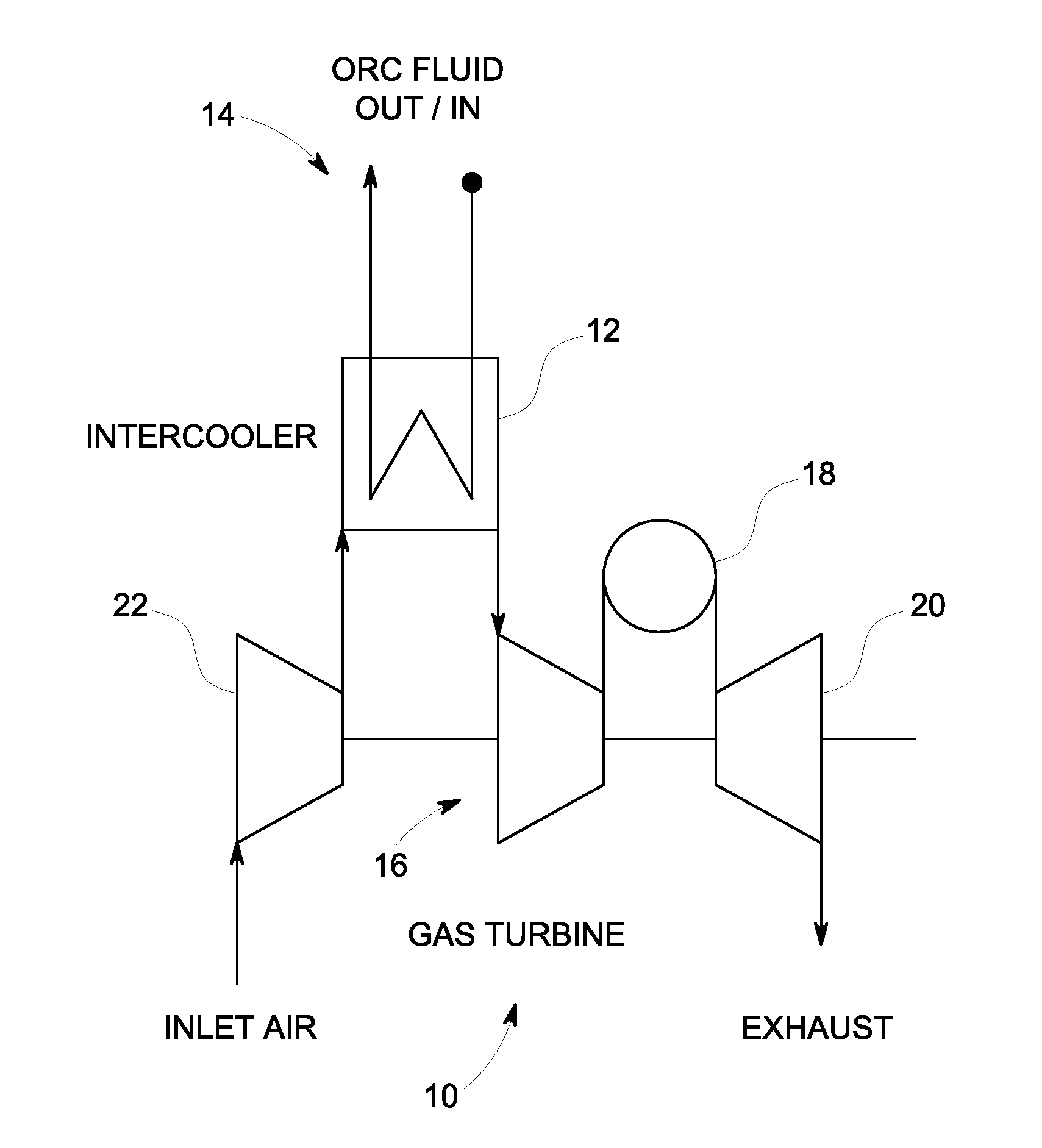
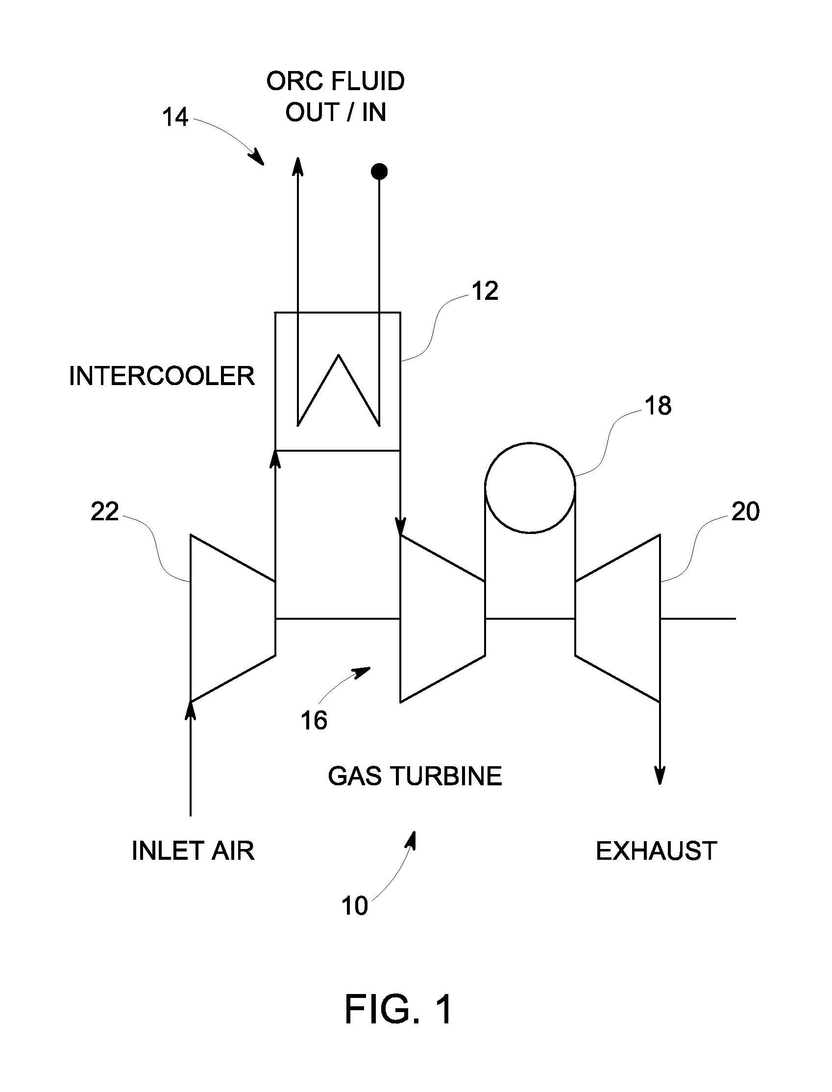
[0023]FIG. 1 is a simplified schematic diagram illustrating a gas turbine 10 including an intercooler 12 configured to heat an ORC fluid 14 according to one embodiment. Gas turbine engine 10 includes, in serial flow arrangement, a compressor 16 for compressing air flowing through the engine, a combustor 18 in which fuel is mixed with the compressed air and ignited to form a high temperature gas stream, and a high-pressure turbine 20. The compressor 16, combustor 18 and turbine 20 are sometime collectively referred to as the core engine. At least some known gas turbine engines also include a low-pressure compressor 22, or booster, for supplying compressed air to a high-pressure compressor 16.

[0024]Gas turbine engines are used in many applications, including aircraft, power generation, and marine applications, as stated herein. The desired engine operating characteristics vary, of course, from application to application. Gas turbines alone have a limited efficiency and a significant a...


PUM


Abstract

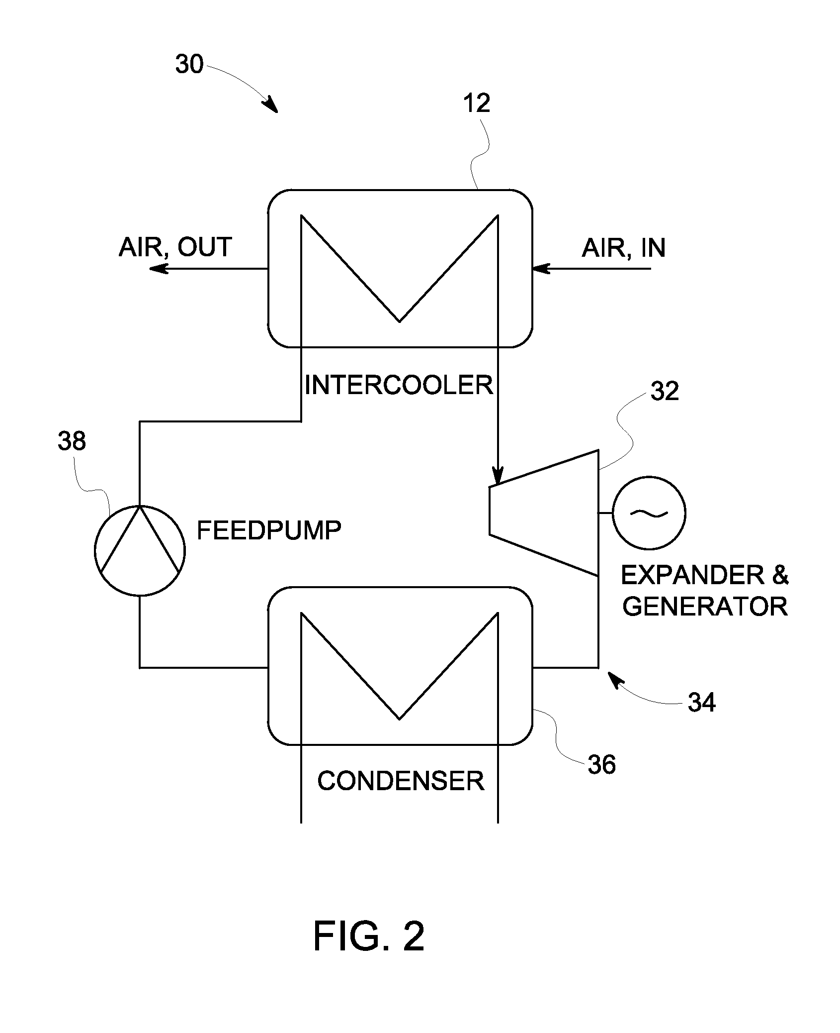
A gas turbine intercooler operates to heat a predetermined organic fluid via heat generated by the gas turbine. The heated organic fluid remains in a partially evaporated or non-evaporated liquid phase to provide a heated organic fluid that reaches a state of saturation with a vapor quality less than unity. An expansion machine expands the heated organic fluid via a Tri-Lateral Flash cycle to increase the vapor quality and generate electrical power therefrom.

Description

BACKGROUND[0001]This invention relates generally to gas turbine engines, and more particularly, to a system and method for extracting and using heat from a gas turbine's intercooler in a specific organic Rankine cycle called Tri-Lateral Flash cycle.[0002]Gas turbine engines generally include, in serial flow arrangement, a high-pressure compressor for compressing air flowing through the engine, a combustor in which fuel is mixed with the compressed air and ignited to form a high temperature gas stream, and a high-pressure turbine. The high-pressure compressor, combustor and high-pressure turbine are sometime collectively referred to as the core engine. At least some known gas turbine engines also include a low-pressure compressor, or booster, for supplying compressed air to the high-pressure compressor.[0003]Gas turbine engines are used in many applications, including aircraft, power generation, and marine applications. The desired engine operating characteristics vary, of course, fr...

Claims


Application Information

Patent Timeline
IPC IPC(8): F02C1/05
CPCF01K25/08F01K21/005
Inventor FREUND, SEBASTIAN WALTERHUCK, PIERRE SEBASTIENFREY, THOMAS JOHANNES
Owner GENERAL ELECTRIC CO
Learn More