
Gas steam generating equipment

A technology for generating equipment and gas steam, which is applied in steam generation, steam boilers, heat exchange equipment, etc., can solve problems such as loss and large energy loss, and achieve the effect of improving heat exchange effect, stable steam output and improving steam quality.

Active Publication Date: 2021-05-07
广东海派节能设备有限公司
View PDF6 Cites 0 Cited by
  • Summary
  • Abstract
  • Description
  • Claims
  • Application Information

AI Technical Summary

Problems solved by technology

[0002] The existing steam generation equipment mainly provides heat for the water in the exchanger through gas heating or electric heating. Compared with the steam generation equipment heated by electric energy, the steam generation equipment using gas heating has a faster response speed and is suitable for large-scale steam supply. advantages, but the use of gas heating will consume a large energy loss in the process of generating steam. In order to further promote the use of steam energy, it is necessary to improve the efficiency of gas-fired steam generation equipment and make full use of the energy released by gas combustion.

Method used


Image

  • Gas steam generating equipment
  • Gas steam generating equipment
  • Gas steam generating equipment

Examples


Embodiment Construction

[0031] The specific embodiments of the present invention will be further described below in conjunction with the accompanying drawings. It should be noted here that the descriptions of these embodiments are used to help understand the present invention, but are not intended to limit the present invention. In addition, the technical features involved in the various embodiments of the present invention described below may be combined with each other as long as they do not constitute a conflict with each other.

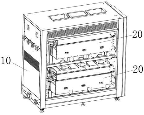
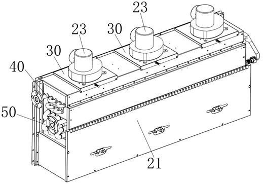
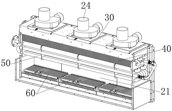
[0032] as attached Figure 1-12 As shown, a kind of gas steam generation equipment provided by the present invention includes a frame 10 and a plurality of steam generation modules 20 arranged in the frame 10. The steam generation module 20 includes a combustion chamber 21, a finned heat exchange 40, tube-and-tube bare-tube heat exchanger 50 and low-nitrogen fire row burner 60, finned heat exchanger 40 and tube-and-tube bare-tube heat exchanger 50 connected in series, f...


PUM


Abstract

The invention discloses gas steam generating equipment, and belongs to the technical field of steam generating equipment. The gas steam generating equipment comprises a plurality of groups of steam generating modules; each steam generating module comprises a combustion chamber, a finned heat exchanger, a tubular light tube heat exchanger and a combustor; the finned heat exchanger, the tubular light tube heat exchanger and the combustor are sequentially arranged in the combustion chamber from top to bottom; the tubular light tube heat exchanger comprises a stratosphere, an upper circulation layer and a lower circulation layer which are arranged from top to bottom; multiple sets of heat exchange light tubes are arranged on different flow layers; the heat exchange light tubes of the stratosphere are sequentially connected in series; and the heat exchange light pipes of the upper circulation layer and the lower circulation layer are alternately connected in series and in communication with the heat exchange light tubes of the stratosphere. Liquid water flows into the tubular light tube heat exchanger from the upper circulation layer after flowing through the finned heat exchanger, absorbs heat in the flowing process to form steam, and alternately and circularly flows between the upper circulation layer and the lower circulation layer, and the heat exchange effect and the steam quality are improved through alternate circulation flow between the upper circulation layer and the lower circulation layer.

Description

technical field [0001] The invention relates to the technical field of steam generating equipment, in particular to a gas steam generating equipment. Background technique [0002] The existing steam generation equipment mainly provides heat for the water in the exchanger through gas heating or electric heating. Compared with the steam generation equipment heated by electric energy, the steam generation equipment using gas heating has a faster response speed and is suitable for large-scale steam supply. However, the use of gas heating will consume a large energy loss in the process of generating steam. In order to further promote the use of steam energy, it is necessary to improve the efficiency of gas-fired steam generation equipment and make full use of the energy released by gas combustion. Contents of the invention [0003] In order to overcome the defects in the prior art, the present invention provides a gas steam generating device. [0004] The technical solution ad...

Claims


Application Information

Patent Timeline
Patent Type & Authority Applications(China)
IPC IPC(8): F22B31/08F28D7/08F28F9/10
CPCF22B31/08F28D7/08F28F9/10
Inventor 张火炬庞长兴国熠陈伟雄成海峰丛日旭胡锐均王启龙伍世良杨国相杨逸
Owner 广东海派节能设备有限公司
Learn More