
Pottery holding device and method

a technology of holding device and pottery, which is applied in the field of pottery, can solve the problems of slipping, twisting or otherwise moving on the device, and not enough three points of contact with the outer surface of the workpiece for some uniquely shaped workpieces

Active Publication Date: 2012-08-30
BAILEY JAMES G
View PDF17 Cites 3 Cited by
  • Summary
  • Abstract
  • Description
  • Claims
  • Application Information

AI Technical Summary

Benefits of technology

The present invention is about a device and method for securely holding a workpiece during rotation of a wheelhead. The device includes a wheelhead member with a bottom surface for engaging the wheelhead and a top surface for accepting the workpiece. It includes at least three holding members that can abut the workpiece and be locked to the wheelhead to hold it securely. The holding members can be moved between a first position where they securely hold the workpiece and a second position where they allow the workpiece to be placed or removed from the wheelhead. The wheelhead member may have magnetic material or a slot for holding the workpiece, and the holding members may have magnets or sliding members for engaging the workpiece. The device can be used with different types of workpieces and can have a variable number of holding members.

Problems solved by technology

One of the drawbacks encountered with prior art wheelhead devices for centering and securely holding workpieces is that they can only provide three points of contact with the outer surface of a workpiece, such as with the Giffin device described above.
While three points of contact may be sufficient to secure circular or three-sided workpieces, three points of contact are not sufficient for some uniquely shaped workpieces.
When these types of irregular or organic workpieces are not fully supported, they may slide, twist or otherwise move on the device during rotation thereof.
Movement of workpieces during rotation prevents a potter from being able to create a circular foot, can break or distort the workpiece, or, in the worst case scenario, can eject the workpiece from the pottery wheel.
Another drawback encountered with prior art wheelhead devices for centering and securely holding workpieces is that the support members of the devices are spatially locked with respect to one another and the center of the device (thus the support members move in unison) and are positioned symmetrically about the center of the device.
In such a fixed symmetric relationship, the support members are unable to fully support an irregular or organic workpiece—as it is likely that only two support members will contact a workpiece.
Similarly, even symmetric non-circular workpieces will not be fully supported by the fixed symmetrically disposed support members of these prior art devices.
At this stage, the workpiece is not fully supported.
However, because the workpiece is non-circular, the true center of the workpiece is not aligned with the center of the device.
In such a non-centered arrangement, a foot cannot be formed in the center of the workpiece, and the potter has no ability to select the position of the foot.
Further, as is understood in the art, such pushing and twisting of the workpiece about the device will scratch, deform or otherwise mar the workpiece.
Still further, in all likelihood, an irregular or non-circular symmetric workpiece will not define three outer surface locations that are radially equidistant from one another and from a central point, and therefore a third support member would never reach the outer surface of such a workpiece (at least without deforming the workpiece).
Yet another drawback encountered with prior art wheelhead devices for centering and securely holding workpieces is that the workpieces, including circular workpieces, cannot be selectively secured in locations other than the center of the device.
Further, the location of the foot of workpieces cannot be chosen by the potter.
As a result, the prior art devices do not allow a potter to select the secured position and orientation of a workpiece, and therefore do not allow the potter to elect where the foot of a particular workpiece should be formed, such as circular workpieces, or apply such an “uneven” glaze process.
Still further, the fixed symmetrical arrangement of the support members of prior art devices does not allow the potter to control where irregular shaped workpieces are secured on the devices (assuming an irregular shaped workpiece can actually be secured).
Even if a prior art wheelhead device can secure a particular irregular or asymmetric workpiece without destroying the workpiece, the workpiece would be automatically positioned (as discussed above), and the potter thus had no ability to select the secured position.
As a result, the prior art devices do not allow a potter to select the secured position and orientation of an irregular or non-circular symmetric workpiece, and therefore do not allow the potter to elect where the foot of a particular irregular or non-circular symmetric workpiece should be formed.
Another drawback encountered with prior art wheelhead devices for centering and securely holding workpieces is that the devices are thick and thereby significantly elevate workpieces with respect to the wheelhead.
Therefore, if a particular pottery wheel includes a splash pan, workpieces that are significantly elevated with respect to the wheelhead will tend to throw trimmings or other debris past or over the splash pan.
Yet another drawback encountered with prior art wheelhead devices for centering and securely holding workpieces is that they only function properly with a particular direction of rotation.
However, the spiral groove is limited to providing movement towards the center of the device only when the support members rotate about the spiral groove either in a clockwise or counter-clockwise direction, depending upon if the spiral groove spirals from the outer edge to the center in a clockwise or counter-clockwise direction.
As a result, if a clockwise designed prior art device were installed on a pottery wheelhead that rotated counter-clockwise, the support members would be biased away from the workpiece during rotation of the wheelhead, and thus fail to support the workpiece.
The same lack of support would occur if a counter-clockwise designed prior art device were installed on a pottery wheelhead that rotated clockwise.

Method used


Image

  • Pottery holding device and method
  • Pottery holding device and method
  • Pottery holding device and method

Examples


first embodiment

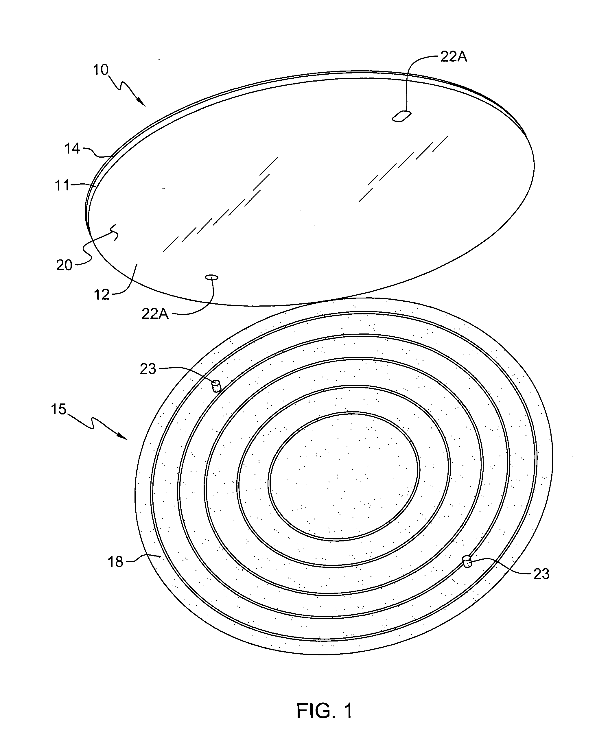
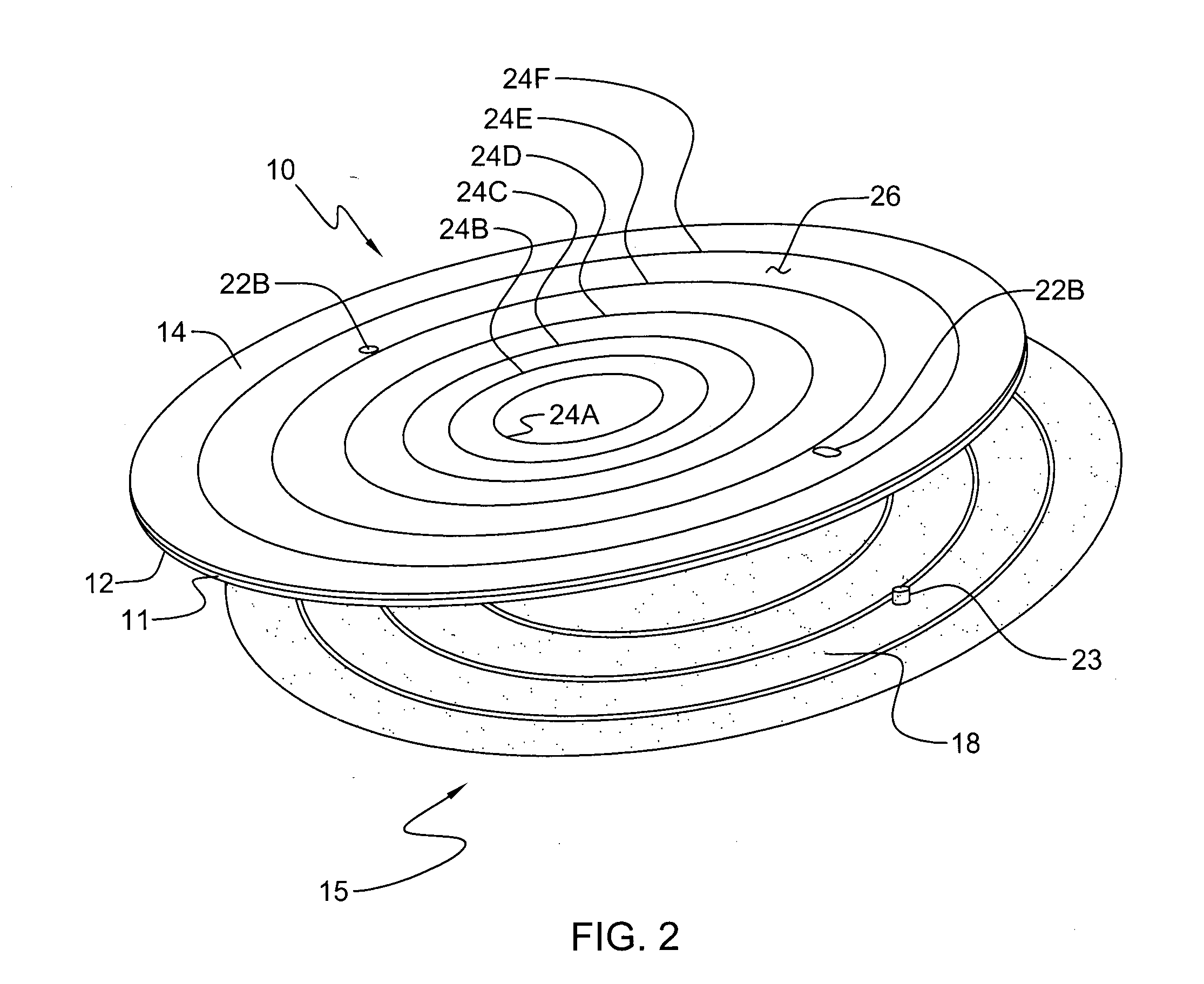
[0055]In FIGS. 1-6, a pottery holding device assembly embodying the present invention is indicated generally by the reference numeral 10. As shown in FIGS. 1-6, the pottery holding device 10 includes an exemplary wheelhead member 11 and at least four exemplary potter holding members 16. The wheelhead member 11 includes an exemplary bottom disc 12 and an exemplary top disc 14.

[0056]As shown in FIG. 1, the bottom disc 12 is preferably configured to be applied to the top surface of a wheelhead 18 of a pottery wheel, such as exemplary pottery wheel 15. As such, exemplary bottom disc 12 may include a planar exemplary wheelhead or bottom surface 20 sized and shaped comparable to the top surface of wheelheads. Because wheelhead sizes and shapes may differ in the marketplace, bottom disc 12 may be any size and shape that substantially corresponds to an existing wheelhead. For example, typical wheelheads are circular with diameters ranging from about 7 inches to about 16 inches, and more typ...

second embodiment

[0072]In FIG. 7, another exemplary pottery holding device embodying the present invention is indicated generally by the reference numeral 110. The exemplary pottery holding device 110 is substantially the same as the exemplary pottery holding device 10 described above with reference to FIGS. 1-6, and therefore like reference numerals preceded by the numeral “1” are used to indicate like elements. The bottom disc 112 and top disc 114 of the wheelhead member 111 of the pottery holding device 110 are the same as the pottery holding device 10, and therefore the illustrations of FIGS. 1-6 and the associated detailed description of the bottom disc 12 and top disc 14 equally apply to the pottery holding device 110 of FIG. 4. The exemplary pottery holding device 110 differs from the exemplary pottery holding device 10 with respect to the configuration of the holding members 116. In pottery holding device 110, the exemplary at least three holding members 116 (four holding members 116 illustr...

third embodiment

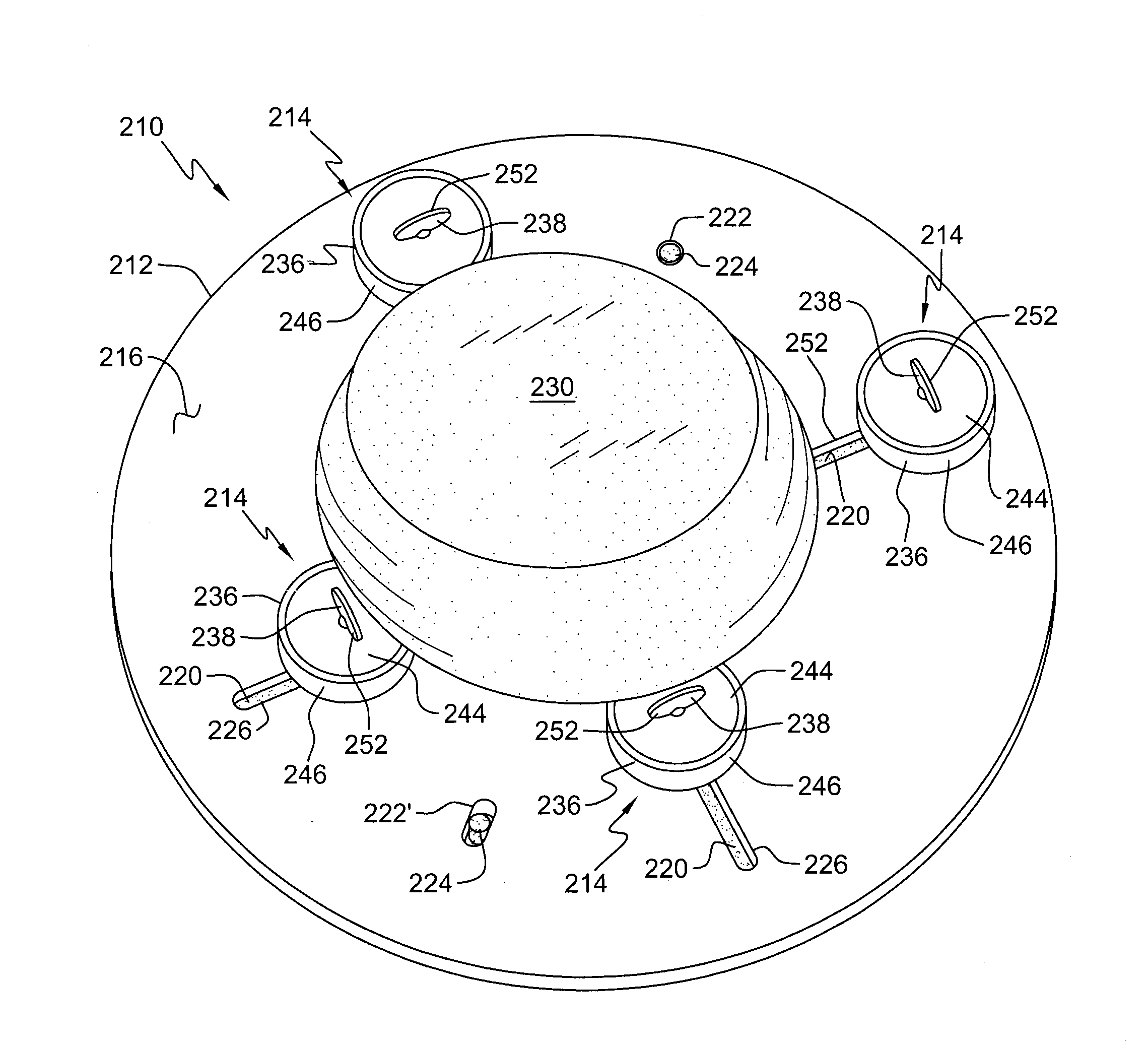
[0075]In FIGS. 8-14, another exemplary pottery holding device embodying the present invention is indicated generally by the reference numeral 210. Exemplary pottery holding device 210 includes an exemplary wheelhead member 212 and at least three exemplary pottery holding members 214 disposed on the wheelhead member 212. In the illustrated embodiment, the exemplary illustrated potter holding device 210 includes four exemplary pottery holding members 214 disposed on the wheelhead member 212. However, less than three and more than four exemplary pottery holding members 214 may be provided.

[0076]As shown in FIGS. 8 and 11-14, the top surface of the wheelhead member 212 defines an exemplary working surface 216, and as shown in FIGS. 9 and 10, the bottom surface of the wheelhead member 212 defines an exemplary wheelhead surface 218. The wheelhead member 212 is preferably configured to be applied to the top surface of a wheelhead 220 of a pottery wheel, as shown in FIGS. 8 and 12-14. As su...


PUM

PropertyMeasurementUnit
diametersaaaaaaaaaa
diametersaaaaaaaaaa
diameteraaaaaaaaaa

Abstract

A pottery holding device and method for securely holding a workpiece during rotation and working of the workpiece on a wheelhead of a pottery wheel. The pottery holding device includes a wheelhead member and at least three holding members. The wheelhead member configured for attachment to the wheelhead of a pottery wheel. The at least three holding members and wheelhead member configured to allow selective locking of the at least three holding members in positions about the periphery of a workpiece. The device adapted to securely hold circular, non-circular symmetric and irregular, asymmetric or organic shaped workpieces. The device further adapted to securely hold workpieces in positions and orientations such that the center of the workpieces is aligned with the axis of rotation of the device, and positions and orientations such that the center of the workpieces is spaced from the axis of rotation of the device.

Description

FIELD OF THE INVENTION[0001]The present invention relates to the field of pottery, and, in particular, to devices and methods for selectively securing a preformed shape of pottery to the wheelhead of a pottery wheel during rotation.BACKGROUND INFORMATION[0002]A pottery wheel, also known as a potter's wheel or potter's lathe, is a machine used to facilitate forming, trimming, decorating and other manipulation techniques of pottery. At a basic level, a potter's wheel is a device that provides rotation to a workpiece or “form”, such as an unformed piece of clay or a preformed shape. As the art of pottery has existed for centuries, pottery wheels have taken many different forms. A typical modern-day pottery wheel includes a frame, a power source (such as a motor or kickwheel) and a wheelhead coupled to the power source such that the power source rotates the wheelhead. Some pottery wheels include attached work tables and splash pans that surround the wheelhead to catch any trimmings or o...

Claims


Application Information

Patent Timeline
Patent Type & Authority Applications(United States)
IPC IPC(8): B28B17/00B23B31/10B28B1/02
CPCB28B1/025B28B17/00Y10S425/033Y10S425/12Y10T409/3056Y10T409/305544Y10T29/49998Y10T279/26Y10T82/26Y10T409/305656Y10T82/262Y10T82/30
Inventor BAILEY, JAMES G.
Owner BAILEY JAMES G
Learn More