
Solar tracker drive

a tracker drive and solar energy technology, applied in the direction of motor/generator/converter stopper, electric controller, dynamo-electric converter control, etc., can solve the problem of corresponding collectors being rotated to an incorrect position, and achieve the effect of less cos

Inactive Publication Date: 2012-08-30
SUNPOWER CORPORATION
View PDF9 Cites 58 Cited by
  • Summary
  • Abstract
  • Description
  • Claims
  • Application Information

AI Technical Summary

Benefits of technology

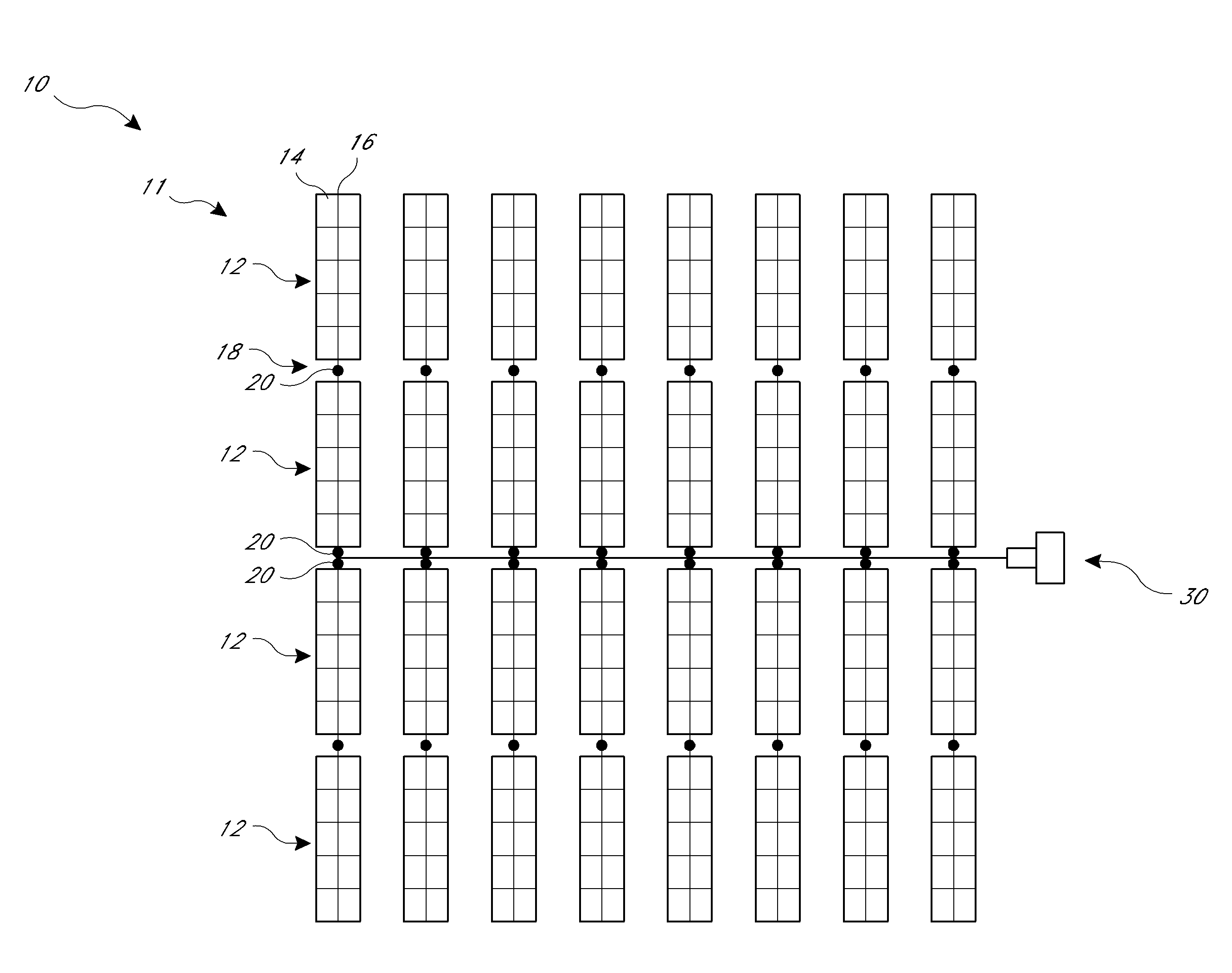
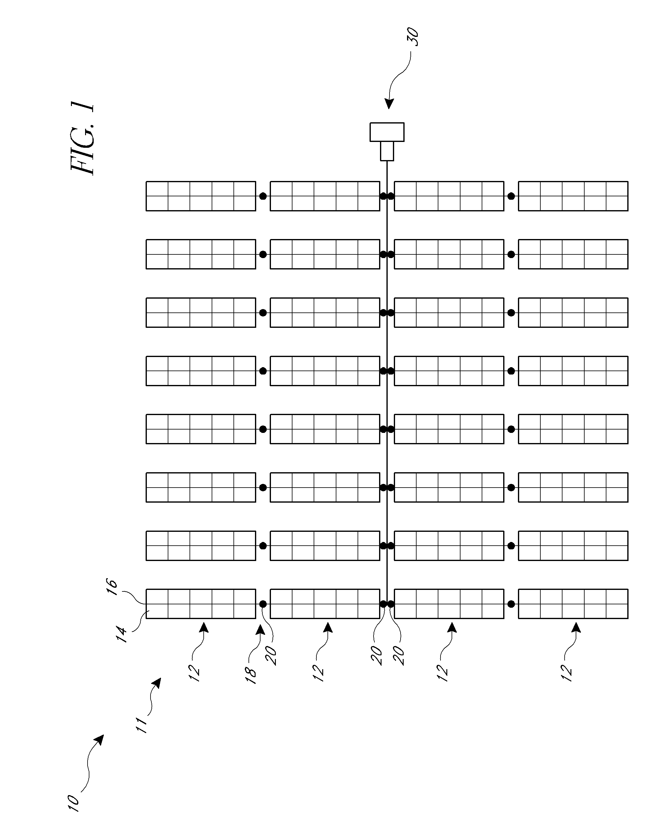
[0006]An aspect of at least one of the inventions disclosed herein includes the realization that certain labor-intensive tasks that have previously been performed on the construction site of a photovoltaic system, can be performed more quickly, accurately, and / or with less cost if certain activities can be performed in a controlled environment, such as a manufacturing facility. For example, one step of constructing a concentrated photovoltaic system is the calibration of the sun-tracking drives. Each of the motors include an inclination sensor (inclinometer) which provides an output for indicating the rotational position of each collector module. However, if an inclinometer is not properly calibrated, the corresponding collector would be rotated to an incorrect position. As noted above, an error as little as one-half or 0.1° can significantly impact efficiency.
[0007]One approach to calibrating such drives is to manually rotate a collector to a reference position, such as “stowed” or level position and using an accurate level or other calibrated high-accuracy inclinometer to confirm the accuracy of the output of an attached inclinometer, through the full range of motion of the collector. This procedure would be repeated for every sun-tracking drive in an solar power farm. However, the installation sites for solar facilities can be in remote locations, subject to hot weather, and can be grounds for wildlife, such as snakes. Thus, reducing the labor to be performed in such locations can significant reduce labor costs.

Problems solved by technology

However, if an inclinometer is not properly calibrated, the corresponding collector would be rotated to an incorrect position.
However, the installation sites for solar facilities can be in remote locations, subject to hot weather, and can be grounds for wildlife, such as snakes.

Method used


Image

  • Solar tracker drive
  • Solar tracker drive
  • Solar tracker drive

Examples


Embodiment Construction

[0025]The following detailed description is merely illustrative in nature and is not intended to limit the embodiments of the subject matter or the application and uses of such embodiments. As used herein, the word “exemplary” means “serving as an example, instance, or illustration.” Any implementation described herein as exemplary is not necessarily to be construed as preferred or advantageous over other implementations. Furthermore, there is no intention to be bound by any expressed or implied theory presented in the proceeding technical field, background, brief summary, or the following detailed description.

[0026]Certain terminology may be used in the following description for the purpose of reference only, and thus are not intended to be limiting. For example, terms such as “upper”, “lower”, “above”, and “below” refer to directions in the drawings to which reference is made. Terms such as “front”, “back”, “rear”, and “side” describe the orientation and / or location of portions of...


PUM


Abstract

A solar energy collection system can include a drive configured to adjust a tilt position of a solar collector assembly so as to tract the sun. The drive can include hardware for providing feedback control of the orientation of the solar collector assembly. A method for calibrating the drive can include moving the drive to a reference position and saving an output value from a sensor configured to detect the orientation of the drive. The reference value output from the sensor can then be used in determining the target output value from the sensor required to achieve a desired orientation.

Description

CROSS-REFERENCE TO RELATED APPLICATIONS[0001]This application is based on and claims priority to U.S. Provisional Patent Application No. 61 / 445,181, filed on Feb. 22, 2011, the entire contents of which is hereby expressly incorporated by reference.TECHNICAL FIELD[0002]Embodiments of the subject matter described herein relate generally to solar energy systems which include drive systems for sun tracking, solar energy collecting devices.BACKGROUND[0003]Some larger solar collector installations include an array of sun tracking, solar power collector assemblies. Such assemblies can be used in conjunction with photovoltaic modules, concentrated photovoltaic modules, as well as concentrated thermal solar collector devices.[0004]Such sun-tracking collectors include hardware for automatically adjusting the position of the collector devices to track the sun as it moves across the sky. This tracking movement can be accomplished in a number of different ways. Some systems use a single axis tra...

Claims


Application Information

Patent Timeline
IPC IPC(8): H01L31/042G05B11/01F24S10/80F24S50/20
CPCF24J2/38Y02E10/52F24J2002/385F24J2/407F24J2/541Y02E10/47F24S30/425F24S50/20F24S50/80F24S2050/25H02S20/10H02S20/32Y02E10/50
Inventor ALMY, CHARLESBARTON, NICHOLAS
Owner SUNPOWER CORPORATION
Learn More