Device and method for electron beam energy verification

Active Publication Date: 2012-08-30
ETHICON INC
View PDF4 Cites 8 Cited by
  • Summary
  • Abstract
  • Description
  • Claims
  • Application Information

AI Technical Summary

Benefits of technology

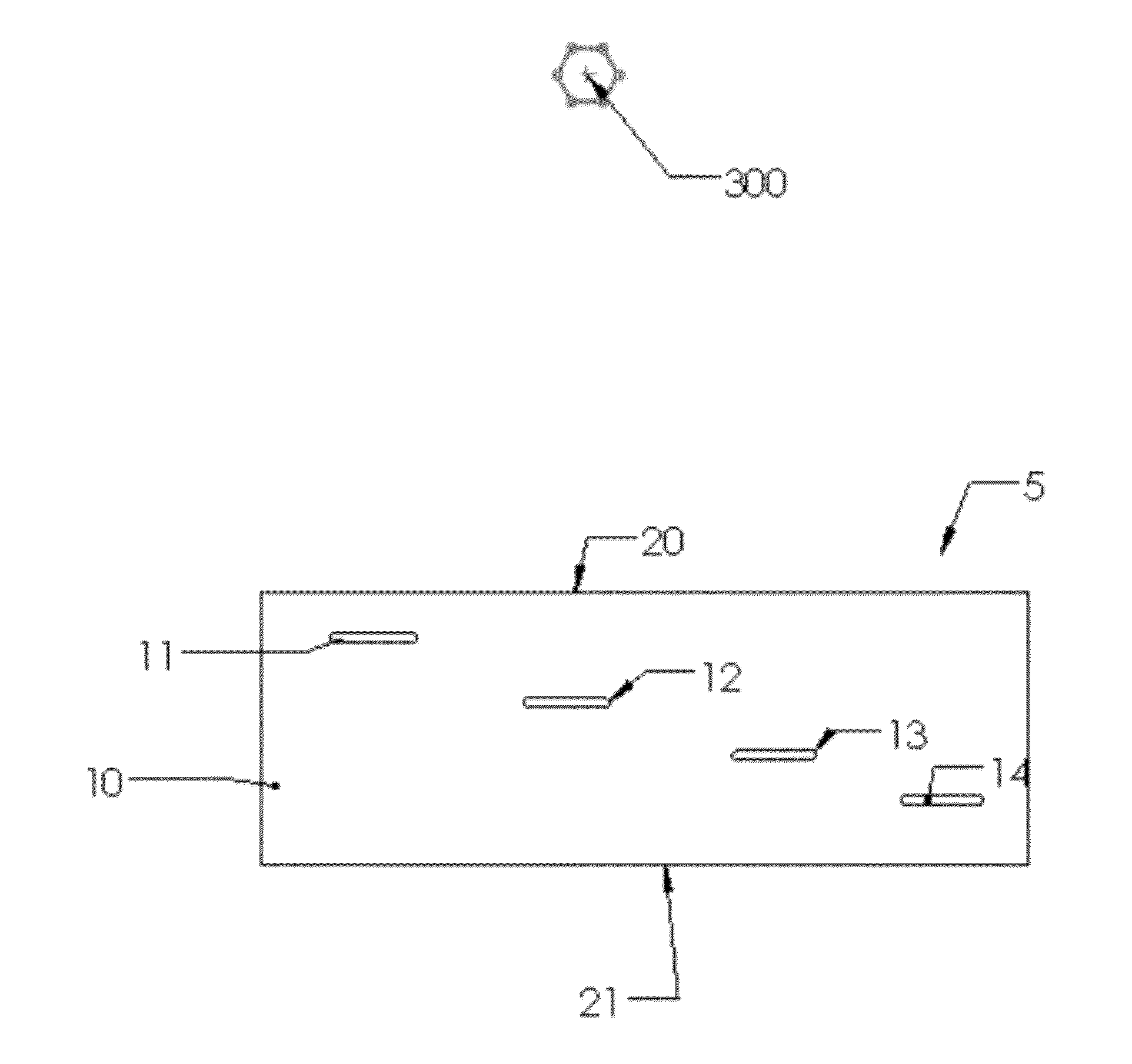
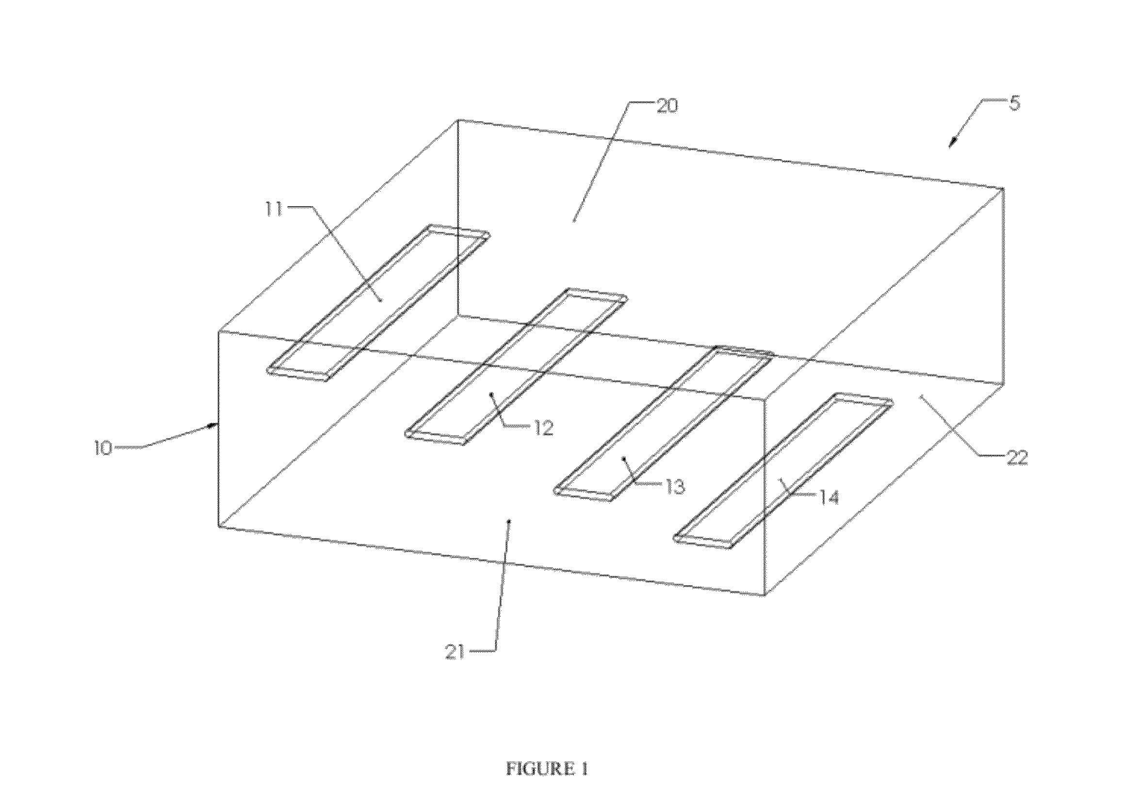
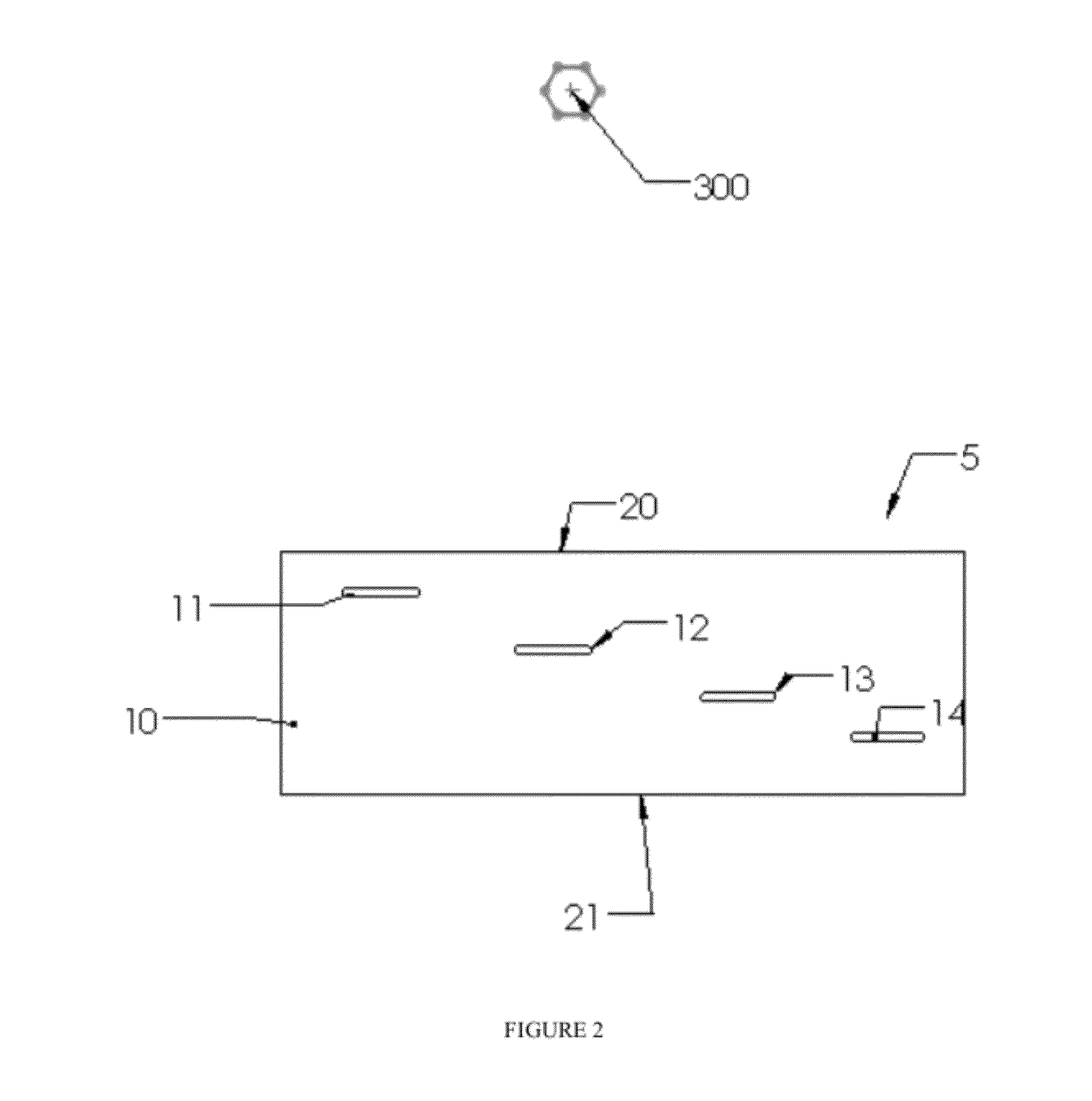
[0026]According to an embodiment of the current invention, a device and system for verifying the electron beam kinetic energy spectrum and determining changes in kinetic electron beam energy spectrum comprises a radiation-absorbing mass defined by a top surface, a bottom surface, and side wall

Problems solved by technology

Products may have components which are adversely affected by exposure to radiation above pre-determined levels (e.g., biologics) and variations in the radiation absorption applied to those products may greatly influence their functionality.
However, techniques known to directly measure electron kinetic-energy and related kinetic energy spectrum are labor intensive, expensive and have difficulty in diagnosing subtle changes in electron beam energy.
Currently, technologies are not readily available to be utilized as a benchmark to diagnose changes in the electron beam energy.
Currently, automated systems are available to remove or reduce the human element, however, these systems are very expensive, take experience to utilize said systems, and are difficult to transport to an array of processing sites.
The current measurement of energy is performed very infrequently (monthly or quarterly) which can lead to process changes that could potentially impact the validated state of the process.
The methodology in ISO / ASTM 51649 requires numerous dosimetry measurements or requires the use of specialized film reading equipment and substantial investment of time and highly specialized skills are required; therefore, this measurement is performed on a very sparse basis.

Method used


Image

  • Device and method for electron beam energy verification
  • Device and method for electron beam energy verification
  • Device and method for electron beam energy verification

Examples


example 1

[0072]Experimental Irradiation Absorbed Dose Measurements for two different accelerators are presented in Tables 1 and 2, using the device comprising two stepped plates. Referring now to graph shown in FIG. 11, comparative dose profile for two electron accelerators is shown as relative dose relative to depth aluminum block of the inventive device 5, with large squares corresponding to accelerator IBA Rhodotron TT100 #2, calibrated by conventional wedge technologies as 10.0 MeV, and with smaller rhombs corresponding to accelerator IBA TT00 #1, calibrated by conventional wedge technologies as 10.4 MeV. The graph shown in FIG. 11 and Tables reflect kinetic energy differences between two electron accelerators with primary kinetic energy differences of only 4% as measured by conventional wedge technologies: IBA TT00 #1: 10.4 MeV; IBA Rhodotron TT100 #2: 10.0 MeV.

[0073]Using the present device and method, looking at the mean dose ratio in scaled results, especially at positions 3 and 4, o...

example 2

[0074]Results of experiments with device comprising two stepped plates over seven days are presented in Tables 3-5

TABLE 3Experimental Dose Measurements, kGy, Days 1-2Day 1Day 2Depth inTestTestTestTestTestTestA1 block111009-1111009-2111009-3111109-1111109-2111109-3Position(cm)kGykGykGykGykGykGy10.43.103.153.073.133.163.1221.03.903.903.923.923.953.9631.42.952.962.993.043.053.1041.71.651.651.651.701.701.72Results scaled to position 210.40.790.810.780.800.800.7921.01.001.001.001.001.001.0031.40.760.760.760.770.770.7841.70.420.420.420.430.430.43

TABLE 4Experimental Dose Measurements, Days 3-5Depth inDay 3Day 4Day 5A1 block111209-1111209-2111209-3111609-1111709-1111709-2Position(cm)kGykGykGykGykGykGy10.42.972.972.982.973.012.9521.03.743.763.813.723.873.8131.42.892.952.922.872.992.9241.71.611.641.701.661.701.68Results scaled to position 210.40.790.790.780.800.780.7721.01.001.001.001.001.001.0031.40.770.780.770.770.770.7741.70.430.440.450.450.440.44

TABLE 5Experimental Dose Measurements, Days...

example 3

[0075]Summary of the results of 21 tests performed on 7 different days by 4 different associates is presented in Table 6, with the data extracted from Tables 3-5. Data of Table 6 shows that the results are repeatable and reproducible. CV stands for Coefficient of Variation (std dev divided by the average value)

TABLE 6Experimental Dose Measurements summaryDay 1Day 2Day 3Day 4Day 5Day 6Day 7OverallPosition 10.790.800.790.800.770.810.790.79Mean1.2%0.7%0.6%NA0.3%0.2%1.1%1.1%CVPosition 21.001.001.001.001.001.001.001.00Mean0.0%0.0%0.0%0.0%0.0%0.0%0.0%0.0%CVPosition 30.760.780.770.770.770.780.770.77Mean0.2%0.5%1.0%NA0.4%0.8%1.4%1.0%CVPosition 40.420.430.440.450.440.440.430.43Mean0.1%0.1%0.8%NA0.0%0.6%0.5%{circumflex over ( )}0.8%CV


PUM


Abstract

The present invention is directed to a device and system for verifying the electron beam kinetic energy spectrum and determining changes in kinetic electron beam energy spectrum that comprises a radiation-absorbing mass defined by a top surface, a bottom surface, and side walls, said mass having at least four separate slots containing one or more of dosimeter strips, wherein said slots are located at different depths within the mass as measured from the top surface of the mass, and said slots are positioned substantially parallel to the top surface of the mass. The present invention also relates to a method of determining and comparing changes in a kinetic electron energy spectrum.

Description

FIELD OF THE INVENTION[0001]The present invention is directed to a device, system and methods for verifying the electron beam kinetic energy spectrum and determining changes in kinetic electron beam energy spectrum, particularly for use in system for sterilizing healthcare products (e.g. medical devices, pharmaceuticals, combination products).BACKGROUND OF THE INVENTION[0002]Many products are irradiated using industrial irradiators such as electron beam (e-beam) sterilizers. Electron beam accelerators are used in a variety of applications such as pharmaceutical / medical device sterilization, food and cosmetic sanitization, industrial cross-linking and gem treatment. Industrial electron beam irradiators accelerate electrons through products such as pharmaceuticals, biologics, and medical devices as said products move in front of the radiation source (i.e. scan horn). The electron's kinetic energy is measured in electron volts. The radiation kinetic energy (electron volts), number of e...

Claims


Application Information

Patent Timeline
IPC IPC(8): H01J47/00
CPCG01T1/08G01T1/169A61L2202/14A61L2/087G01T1/29
Inventor LUXICH, PENNYSAYLOR, MICHAEL C.
Owner ETHICON INC
Why Eureka
Try Eureka