
Magnetic core, current sensor provided with the magnetic core, and current measuring method

a technology of magnetic core and current sensor, which is applied in the direction of instruments, cores/yokes, inductances, etc., can solve the problems of increasing the size and cost of the current sensor, and achieve the effect of enhancing the detection sensitivity of the current sensor

Inactive Publication Date: 2012-08-30
ORMON CORP
View PDF9 Cites 14 Cited by
  • Summary
  • Abstract
  • Description
  • Claims
  • Application Information

AI Technical Summary

Benefits of technology

[0005]The magnetic core 100a of FIG. 17A is provided with the cut-off section 101 that cuts off the magnetic core 100a, and the magnetic impedance element 103 is placed in the cut-off section 101. This has to make a width of the cut-off section 101 large, thus causing deterioration in sensitivity of the magnetic core 100a. The current leakage sensor provided with the magnetic core 100a of FIG. 17A thus has a low detection sensitivity.

Problems solved by technology

However, the current sensor of Japanese Unexamined Patent Publication No. 2005-49311 shields a magnetic core with a shield plate to enhance noise resistance, and increases the size and cost of the current sensor.

Method used


Image

  • Magnetic core, current sensor provided with the magnetic core, and current measuring method
  • Magnetic core, current sensor provided with the magnetic core, and current measuring method
  • Magnetic core, current sensor provided with the magnetic core, and current measuring method

Examples


Embodiment Construction

[0097]Hereinafter, one or more embodiments of the present invention will be described with reference to the drawings. For the sake of convenience of explanation, a member having the same function as the member shown in the drawings is provided with the same symbol and its explanation will be omitted.

1. About Magnetic Core 1

1-1. Schematic Structure of Magnetic Core 1

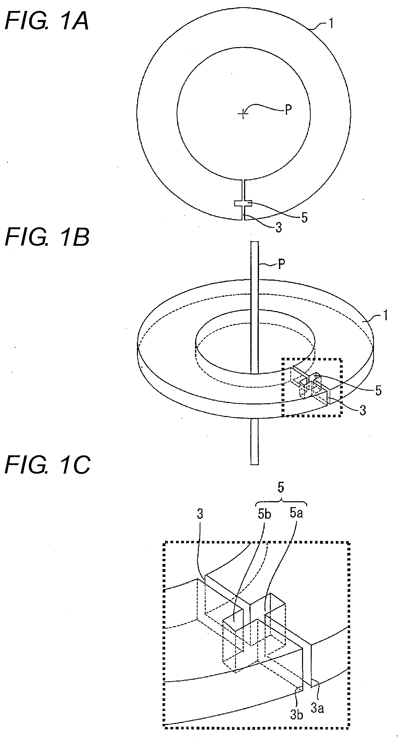
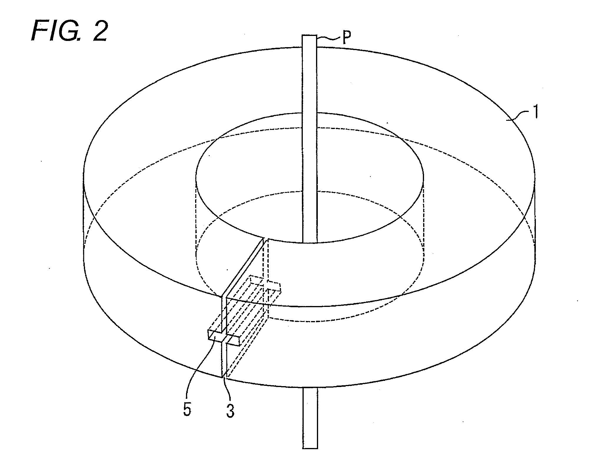
[0098]Hereinafter, a schematic structure of the magnetic core 1 according to the present embodiment will be described. It is to be noted that in order to facilitate understanding, a current sensor provided with the magnetic core 1 will be first described, and the schematic structure of the magnetic core 1 will then be described.

[0099]First, a description of a basic principle of the current sensor will be given below. A magnetic core formed of a magnetic body amplifies a magnetic field generated from a current of a measuring object wire. Next, the magnetoelectric conversion element detects a magnetic flux density of the am...


PUM


Abstract

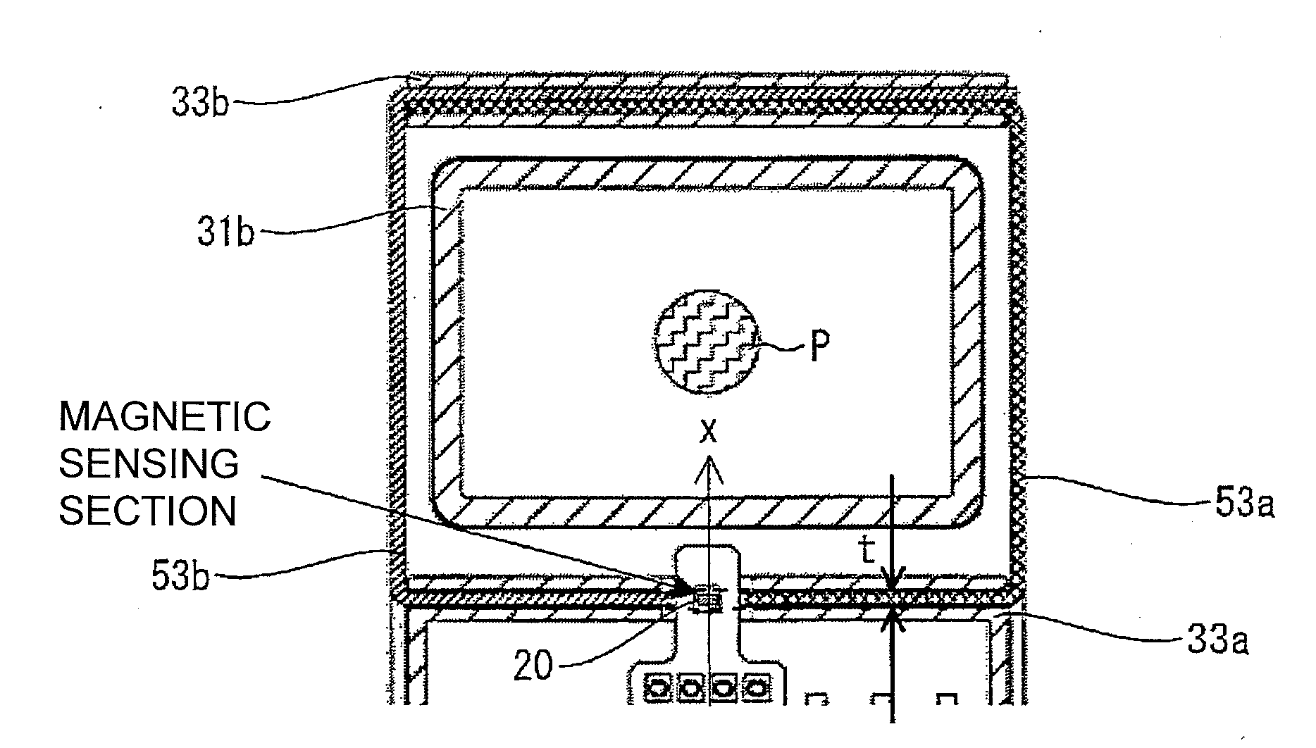
A magnetic core to be used in a current sensor includes a first open end plane, which has a first element holding hole for holding a magnetoelectric conversion element formed therein, and a second open end plane, which has a second element holding hole for holding the magnetoelectric conversion element formed therein, and which faces the first open end plane. With such configuration, the magnetic core can improve the detection sensitivity of the current sensor.

Description

TECHNICAL FIELD[0001]The present invention relates to a magnetic core capable of enhancing detection sensitivity of a current sensor, a current sensor provided with the magnetic core, and a current measuring method.BACKGROUND ART[0002]In recent years, current sensors are in use in a large number of industrial fields, and a demand for high sensitivity, and the like is in increase year by year. Hence, a variety of current sensors have been developed for the purpose of realizing high sensitivity, and one example thereof is disclosed in Japanese Unexamined Patent Publication No. H10-232259.[0003]A current leakage sensor of Japanese Unexamined Patent Publication No. H10-232259 is configured of: a sensor that is made up of a ring-like magnetic body (magnetic core) and senses a change in magnetic field; a magnetic impedance element that is added to the sensor and whose impedance changes in accordance with a variation in magnetic field that occurs in the sensor; and a detector that detects ...

Claims


Application Information

Patent Timeline
Patent Type & Authority Applications(United States)
IPC IPC(8): G01R33/04
CPCG01R15/207H01F2038/305H01F38/30H01F3/14G01R15/20
Inventor NAKA, MAMIKOOKA, KAZUNARIYAMASHITA, TSUKASAITODA, SHUICHI
Owner ORMON CORP
Learn More