

Antenna
a technology of antennas and antennas, applied in the field of antennas, can solve the problems of limited electric power transmission efficiency and low electric power transmission efficiency, and achieve the effects of reducing resistance, stably transmitting electric power, and improving transmission efficiency between antennas
- Summary
- Abstract
- Description
- Claims
- Application Information
AI Technical Summary
Benefits of technology
Problems solved by technology
Method used
Image

Examples
first embodiment
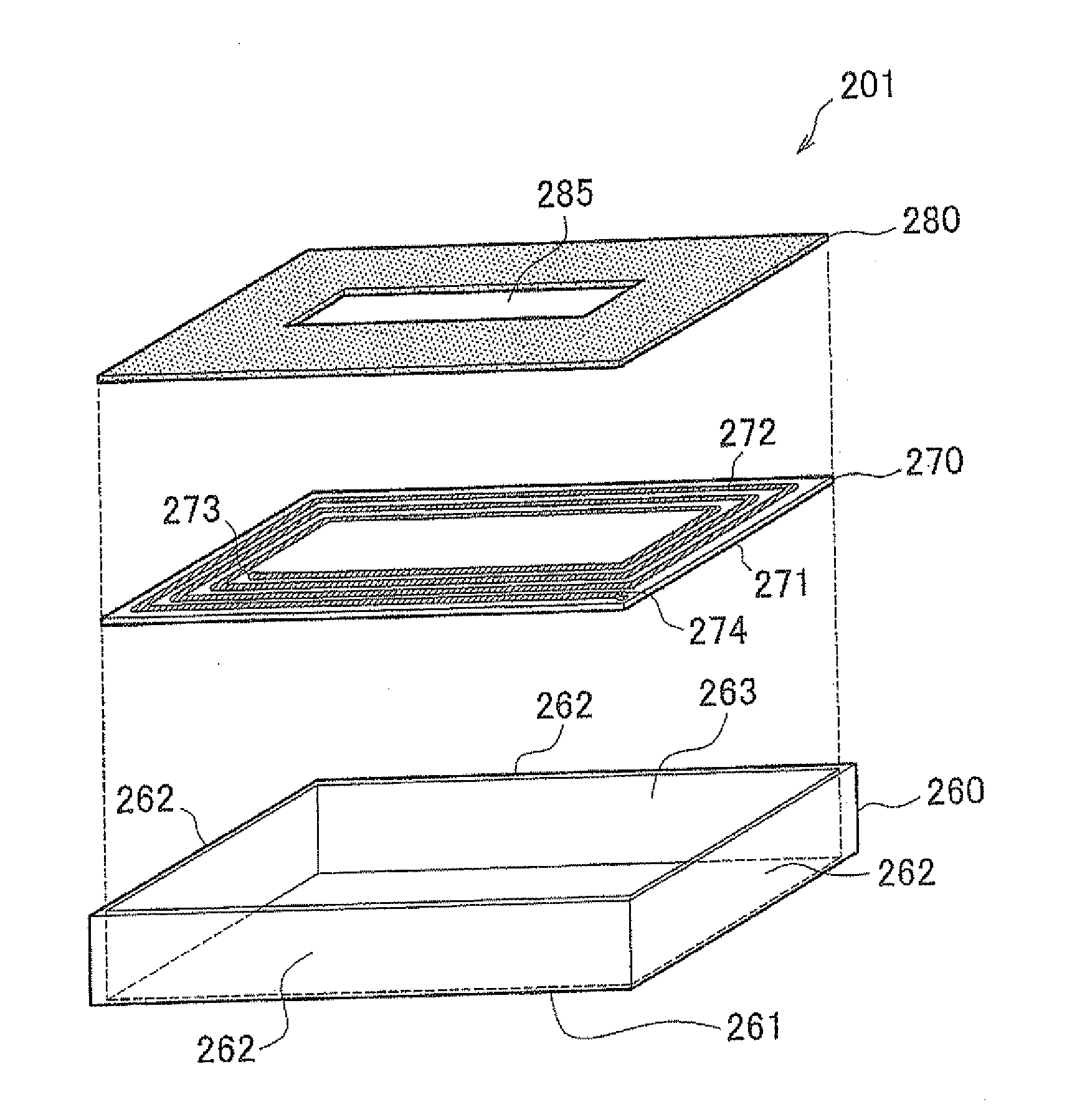
[0066]As described above, according to the receiving antenna 201 of the first embodiment, the magnetic shield body 280 is disposed above the coil unit 270, so that, even when the receiving antenna 201 is installed on the bottom of the vehicle, the influence of the metallic components of the vehicle body is suppressed, which makes it possible to efficiently transmit electric power.
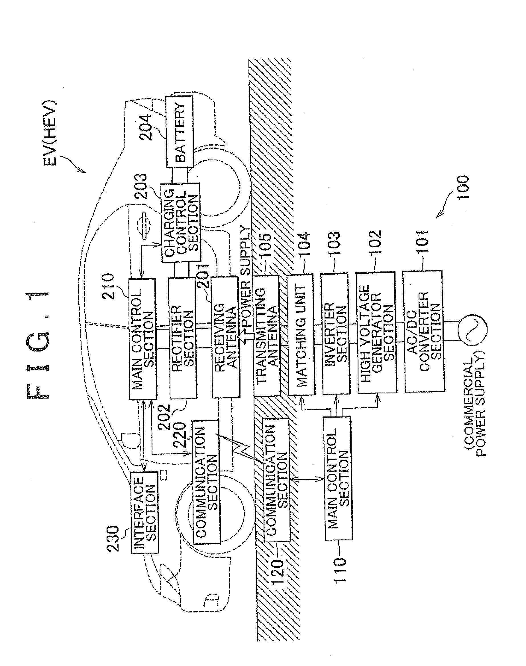
[0067]The structure of the receiving antenna 201 as described above can be applied to the transmitting antenna included in the electric power-transmitting-side system 100. In this case, as shown in FIG. 4, the transmitting antenna is configured so that the transmitting antenna and the receiving antenna 201 are symmetric (mirror symmetric) with respect to a horizontal plane.
[0068]Specifically, when the structure as described above is applied to the transmitting antenna 105, the structure of the transmitting antenna 105 is such that the transmitting antenna 105 includes: a case body 260 having a bottom plate ...
second embodiment
[0071]The heat dissipation member 300 is attached to the side plate portion 262 of the case body 260 of the receiving antenna 201 by fixing means, such as bolts and nuts (not shown). In the antenna a plurality of the heat dissipation members 300 are provided on the side plate portions 262 of the case body 260 so as not to be brought into contact with each other. Specifically, for example, the plurality of heat dissipation members 300 provided on one side plate portion 262 are attached to the side plate portion 262 so as to be spaced apart at predetermined intervals as indicated by g in FIG. 5, for example.
[0072]In view of heat dissipation from the receiving antenna 201 only, it is preferable that the heat dissipation members 300 be arranged without the interval g on the side plate portions 262 of the case body 260. However, in the receiving antenna 201 of the second embodiment, the plurality of heat dissipation members 300 are intentionally arranged so as not to be brought into con...
third embodiment
[0078]Also in the case of the third embodiment, the case body 260 is used to accommodate the coil unit 270 of the receiving antenna 201 having the inductive reactance component. The case body 260 is made of resin, such as polycarbonate, for example, and has a box shape having an opening. A side plate portion 262 is provided so as to extend from each side of a rectangular bottom plate portion 261 of the case body 260 perpendicularly to the bottom plate portion 261. An upper opening portion 263 surrounded by the side plate portions 262 is formed at the upper side of the case body 260.
[0079]Also in the case of the third embodiment, the coil unit 270 includes a rectangular flat plate-shaped glass epoxy base 271 and a spiral, electrically conductive portion 272 formed on the base 271. Conductive wires (not shown), are electrically connected to a first end portion 273 positioned on the radially inner side of the spiral, electrically conductive portion 272, and a second end portion 274 pos...
PUM
 Abstract
Description
Claims
Application Information