
Rotary Reagent Tray Assembly and Method of Mixing Solid-Phase Reagents

a technology of solid-phase reagents and reagent trays, which is applied in the direction of mixing, transportation and packaging, instruments, etc., can solve the problems of affecting the stability of the reagent on the board, not always being able to suspend all solid-phase portions of the reagent adequately, and causing more wear and tear on the system

Active Publication Date: 2012-08-30
SIEMENS HEALTHCARE DIAGNOSTICS INC
View PDF5 Cites 39 Cited by
  • Summary
  • Abstract
  • Description
  • Claims
  • Application Information

AI Technical Summary

Benefits of technology

The patent describes an apparatus and method for agitating liquid containing a solid-phase reagent. The apparatus includes a liquid-bearing container with an internal baffle to create turbulent agitation, a circular tray for rotating containers, and a motor for rotating the tray. The method involves selectively rotating the tray to cause the liquid to flow from one end of the container to the other, promoting suspension or resuspension of the solid-phase reagent. The apparatus and method can be used in various applications such as chemical reactions and biological processes.

Problems solved by technology

However, even with automatic rocking motion, it is not always possible to suspend all solid-phase portions of the reagent adequately.
A further problem with applying a rocking motion is that the motion must be continuously applied to the reagent packs so that the solid-phase portion of the reagent does not settle out.
This “24 / 7” approach produces more wear and tear on the system and also affects the on-board stability of the reagent.
However, “sloshing” due to hurky-jerky centripetal forces can result in solid-phase portions of the reagent adhering to the sides or walls and even to the lid of the liquid-carrying container.

Method used


Image

  • Rotary Reagent Tray Assembly and Method of Mixing Solid-Phase Reagents
  • Rotary Reagent Tray Assembly and Method of Mixing Solid-Phase Reagents
  • Rotary Reagent Tray Assembly and Method of Mixing Solid-Phase Reagents

Examples


Embodiment Construction

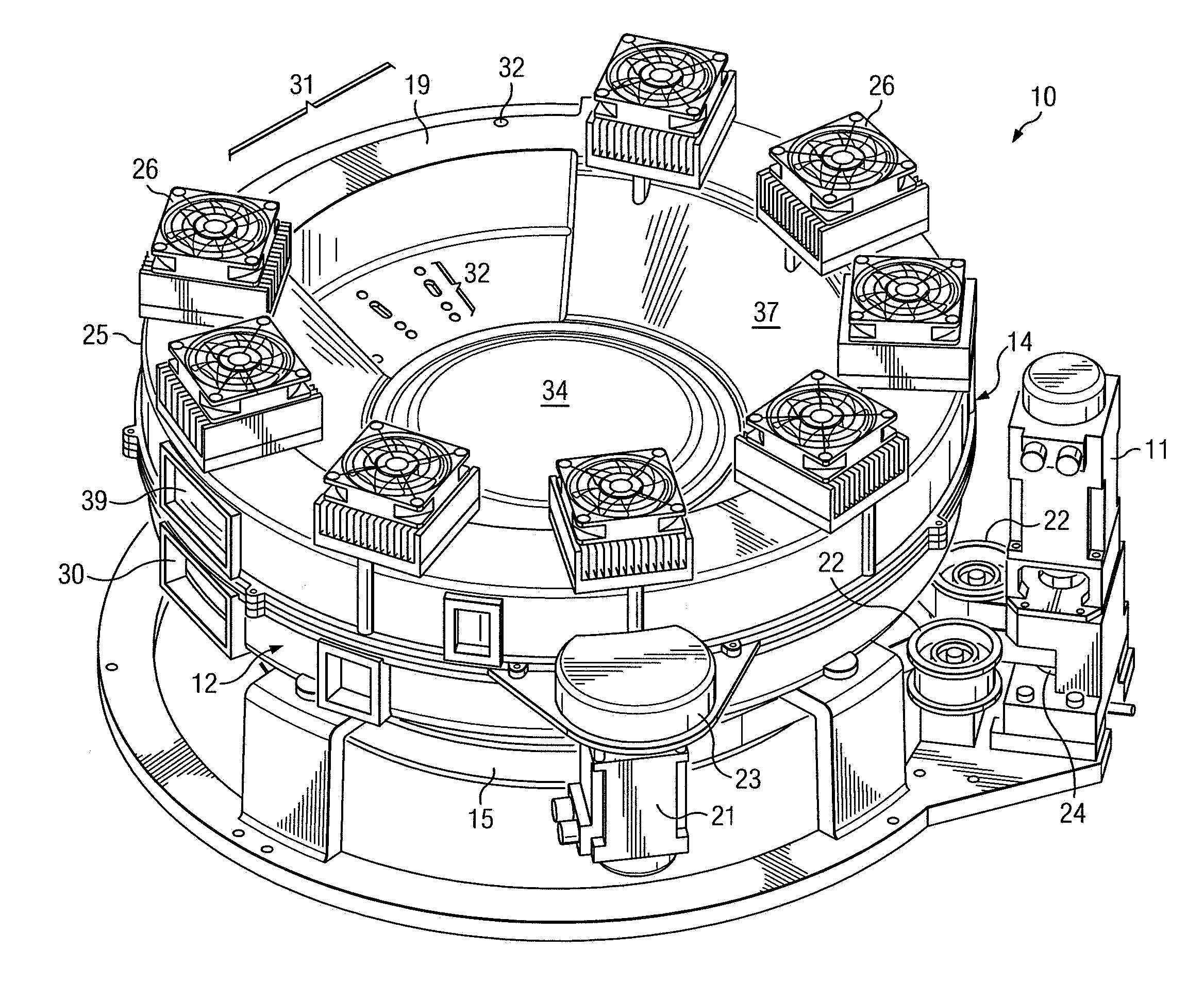
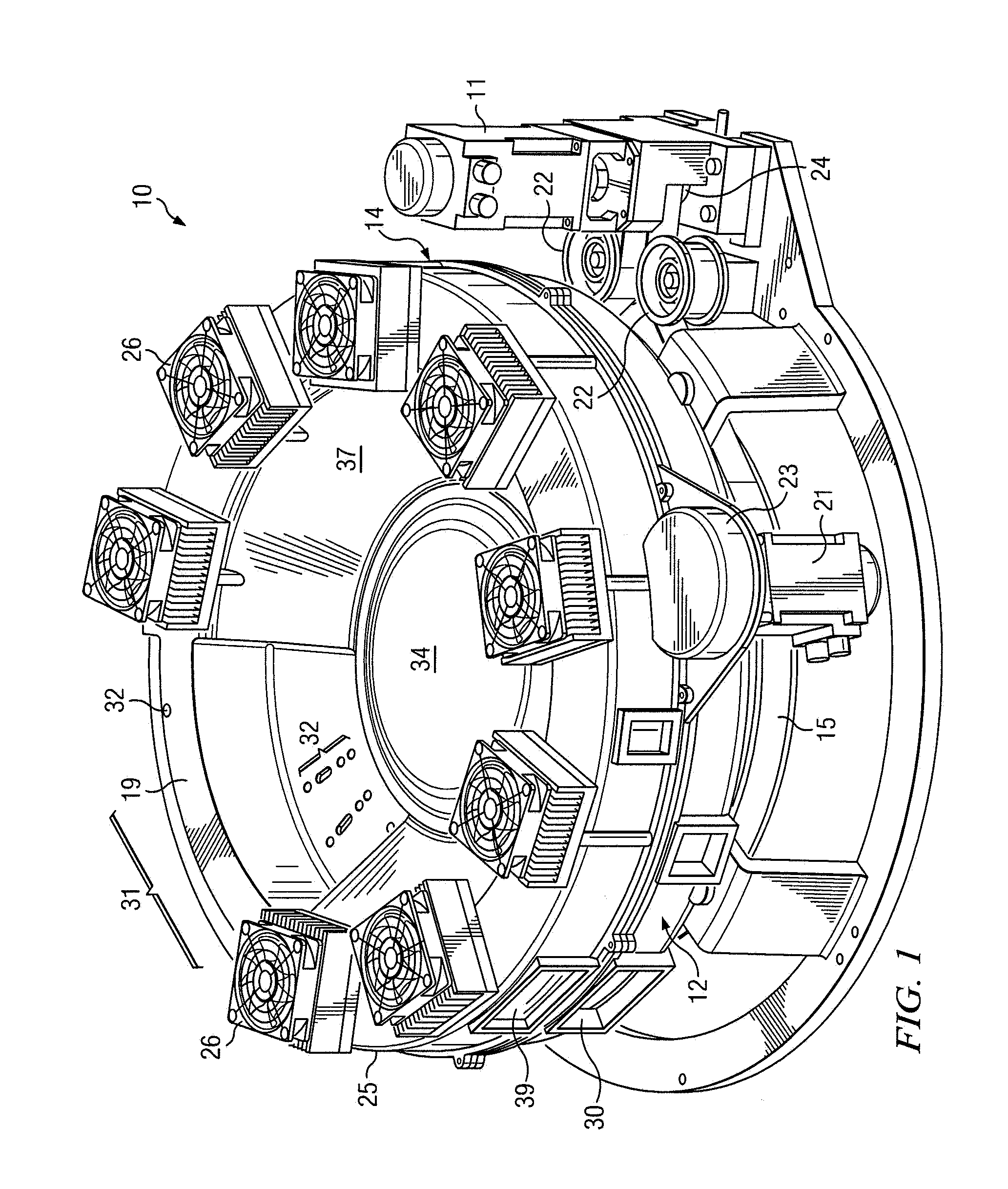
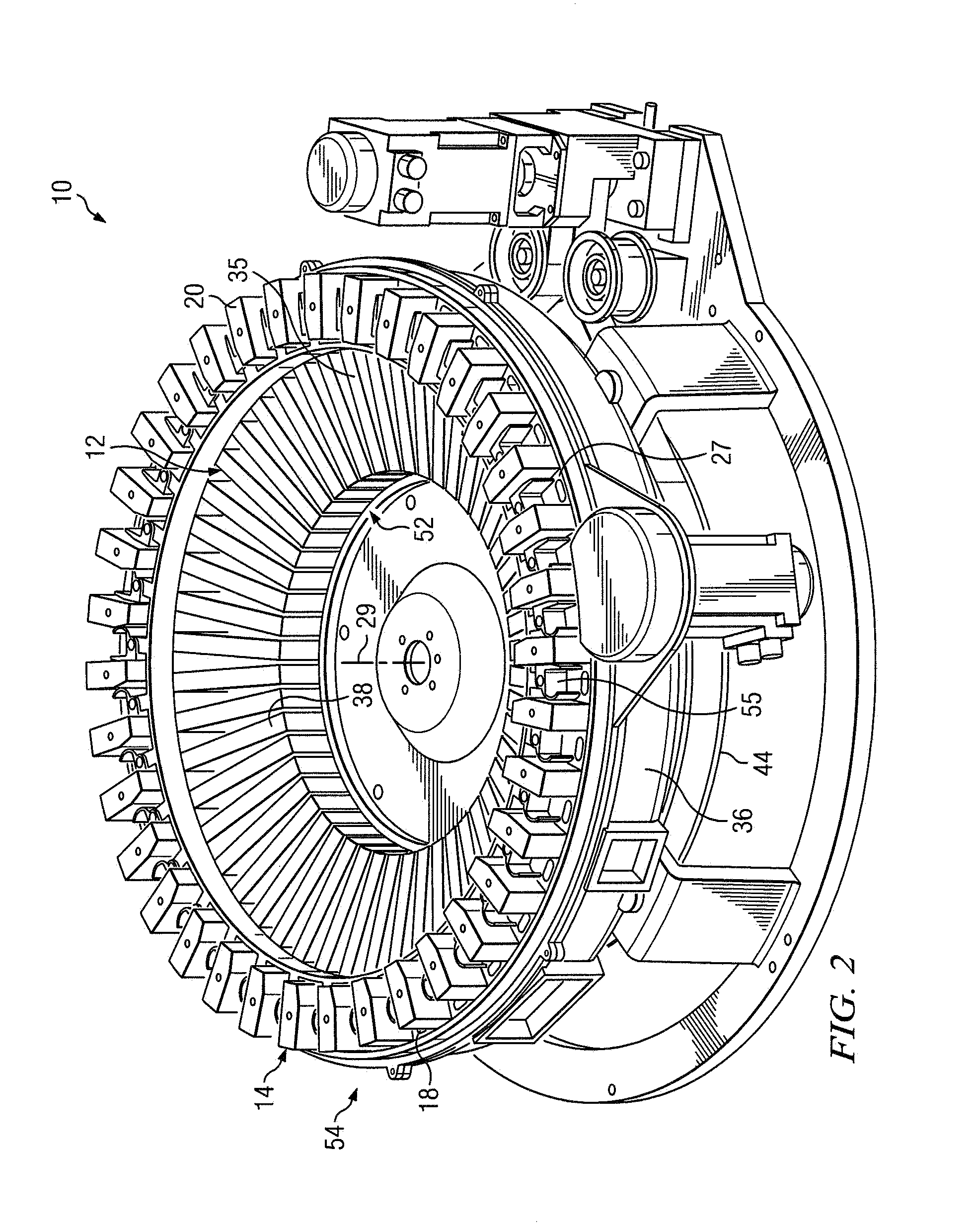
[0021]Referring to FIGS. 1-3, a rotary reagent tray or carousel assembly will be described. The rotary reagent tray assembly 10 is structured and arranged to hold a plurality of primary reagent packs 35 and / or ancillary reagent packs 20, respectively, in a primary tray 12 and an ancillary tray 14. The primary tray 12 and the ancillary tray 14 are arranged in the rotary reagent tray assembly 10 coaxially and concentric with one another about a vertical axis 29. Although the invention will be described in terms of having both a primary tray 12 and an ancillary tray 14, the invention could also be practiced using just a primary reagent tray.

[0022]The primary reagent tray 12 is shown mechanically coupled to a primary motor 11 via a drive shaft 13, a drive pulley 44, and a pulley belt 15. The primary motor 11, drive shaft 13, drive pulley 44, and pulley belt 15 are structured and arranged to provide independent, bi-directional movement to the primary reagent tray 12 by applying torque to...


PUM


Abstract

An apparatus for and method of enabling enhanced, selective agitation of liquid containing a solid-phase reagent. The apparatus includes at least one liquid-bearing container, a circular tray, and a motor. The liquid-bearing container(s) includes at least one internal baffle that imparts turbulent agitation to the liquid when flowing from one end of the container to an opposite end. The circular tray is adapted for selective rotation about a vertical axis of rotation. The rotary circular tray assembly includes container-receiving stations that selectively retain a respective liquid-bearing container in an inclined or pitched orientation with respect to a horizontal plane. The motor creates centrifugal force, which causes liquid in the container(s) to travel from the first end of the container to the second end of the container via the internal baffle(s), agitating the liquid and the solid-phase portions of the reagent. When gravitational force exceeds the centrifugal force, liquid in the container(s) travels from the second end of the container to the first end of the container via the internal baffle(s), again agitating the liquid and the solid-phase portions of the reagent.

Description

STATEMENT REGARDING FEDERALLY SPONSORED RESEARCH OR DEVELOPMENT[0001]Not ApplicableBACKGROUND OF THE INVENTION[0002]The present invention relates to reagent trays for automated immunoassay systems, and more particularly to rotary reagent tray assemblies that are structured and arranged to promote homogenous mixing of solid-phase reagents using rotary motion of the ring and centrifugal force.[0003]Previous immunoassay systems have included linear reagent trays for holding reagent packs, such as ReadyPack reagent packs manufactured by Siemens Healthcare Diagnostics, Inc. of Tarrytown, N.Y. Typically, linear reagent trays are adapted to rock about a point of rotation so that the rocking, back-and-forth motion maintains most of the solid-phase portion of the reagent in suspension. However, even with automatic rocking motion, it is not always possible to suspend all solid-phase portions of the reagent adequately. As a result, some reagent packs must be manually mixed and agitated before ...

Claims


Application Information

Patent Timeline
Patent Type & Authority Applications(United States)
IPC IPC(8): B01F9/10B01F15/06B01F15/00
CPCB01F9/002B01F2009/0092B01F9/0005B01F11/0002B01F11/0005G01N2035/0455B01F2009/0089G01N2035/00445G01N2035/00504G01N2035/0449B01F15/00896G01N35/04G01N2035/0443B01F29/20B01F29/321B01F29/4021B01F29/40221B01F31/10B01F31/20B01F35/5312
Inventor BEHRINGER, BRUCECAMPBELL, ADRIANDUMITRESCU, NICOLAECOHEN, BERI
Owner SIEMENS HEALTHCARE DIAGNOSTICS INC
Learn More