Sealed rolling bearing

Inactive Publication Date: 2012-08-30
NTN CORP
View PDF4 Cites 7 Cited by
  • Summary
  • Abstract
  • Description
  • Claims
  • Application Information

AI Technical Summary

Benefits of technology

[0028]According to the present invention, the check valves provided in the respective seal assemblies serve to cancel negative pressure in the bearing space, and each seal assembly, and the filters

Problems solved by technology

But the sealed rolling bearing disclosed in Patent document 1 has a problem that when the bearing space is brought into communication with the outside of the bearing through the vent means, it is difficult to prevent passage of foreign mat

Method used


Image

  • Sealed rolling bearing
  • Sealed rolling bearing
  • Sealed rolling bearing

Examples


embodiment 1

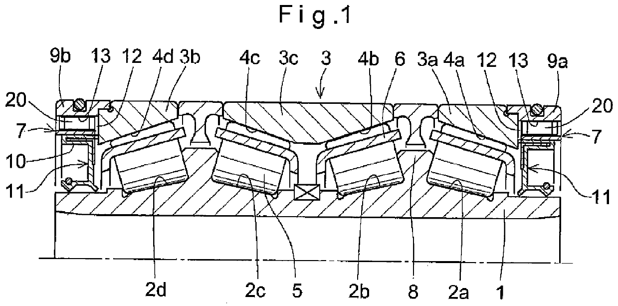
[0043]The sealed rolling bearing of Embodiment 1 is e.g. used to support a roll neck of a rolling mill. The rolling bearing shown is a sealed four-row tapered roller bearing. But the sealed rolling bearing is not limited to such a four-row tapered roller bearing, but may e.g. be a double-row cylindrical roller bearing, a multi-row cylindrical roller bearing, or a single row cylindrical roller bearing.

[0044]The sealed rolling bearing shown comprises two inner races 1 formed with two pairs of raceways 2a and 2b, and 2c and 2d, respectively, two outer races 3a and 3b each formed with a raceway 4a, 4d, an outer race 3c formed with two raceways 4b and 4c, four rows of tapered rollers 5 rollably disposed, respectively, between the four raceways 2a, 2d, 2b and 2c of the inner races 1 and the four raceways 4a, 4d, 4b and 4c of the outer races 3a, 3b and 3c, and four retainers 6 keeping the respective rows of tapered rollers 5 circumferentially spaced apart from each other. Each inner race 1...

embodiment 2

[0072]As shown in FIG. 9, Embodiment 2 includes a plurality of filters 29 are provided at the first end of the valve main body 21 which are spaced apart from one another in the length direction of the valve main body with spacers 33 disposed between the adjacent filters 29. With this arrangement, since the plurality of filters 29 individually trap foreign matter, it is possible to efficiently remove foreign matter.

[0073]In this embodiment, during use of the bearing, water vapor may flow into a space between the radially outer surfaces of the filters 29 and the radially inner surface of the valve main body 21 at the first end, and the water vapor may turn into water drops when the bearing is stopped and the bearing temperature drops or when the air pressure in the bearing changes.

[0074]Embodiment 2 includes means for expelling such water drops in the above gap to the outside of the bearing. As shown in FIG. 9, this means comprises a gap B defined between the radially outer surfaces o...

embodiment 3

[0078]Embodiment 3 includes a cylindrical filter 29 having one end thereof closed by the closed end 22a of the valve body 22 so as be movable together with the valve body 22 with its radially outer surface in sliding contact over its entire circumference with the radially inner surface of the valve main body 21 at its first end.

[0079]In particular, as shown in FIG. 11, the cylindrical filter 29 has one end thereof closed by being fitted in an axial flange 22b formed on the closed end 22a of the valve body 22 along its outer periphery.

[0080]A radially inward step 21c is formed on the radially inner surface of the valve main body 21 at its first end. The filter 29 has its radially outer surface kept in sliding contact with the radially inner surface of the step 21c over its entire circumference. This arrangement increases the exposed surface area of the filter 29 and thus increases its ability to remove foreign matter.

[0081]In this embodiment, water vapor may turn into water drops in ...


PUM

PropertyMeasurementUnit
Lengthaaaaaaaaaa
Pressureaaaaaaaaaa
Flow rateaaaaaaaaaa

Abstract

It is desired to prevent generation of negative pressure in the bearing space and to prevent entry of foreign matter such as water into the bearing. A bearing is provided which includes an inner race (1), an outer race (3), rolling elements (5) disposed between raceways (2 and 4) of the inner and outer races and retained by a retainer (6), and seal assemblies (7) provided at the respective ends of the outer race (3). Each seal assembly (7) includes a seal case (9) fitted on one end of the outer race (3), and an oil seal (11) mounted in the seal case. A check valve (20) is mounted in the seal case (9) which allows only a flow of gas from outside the bearing into the bearing space. A filter (29) is mounted in a flow passage in the check valve which allows passage of gas and prevents passage of liquid and solids.

Description

TECHNICAL FIELD[0001]This invention relates to a sealed rolling bearing for rotatably supporting e.g. a roll neck of a roll used in a rolling machine.BACKGROUND ART[0002]Sealed rolling bearings having seal assemblies for sealing the bearing space defied between the inner and outer races are typically used in an environment where there are large amounts of foreign matter including rolling oil, water and scales, such as for supporting iron-manufacturing pressure rolls used in rolling machines, in order to ensure high lubricity and sealability and prevent entry of foreign matter.[0003]Such sealed rolling bearings are typically four-row tapered roller bearings comprising an inner race, an outer race, tapered rollers disposed between the inner and outer races, a retainer retaining the tapered rollers so as to be circumferentially spaced apart from each other, and seal assemblies.[0004]The seal assemblies each comprise an annular seal case fitted on one end of the outer race, and a seal m...

Claims


Application Information

Patent Timeline
IPC IPC(8): F16C33/76
CPCB21B31/07F16C19/388F16C33/726F16C33/7886F16C33/7813F16C13/02F16C2322/12
Inventor SHIMIZU, YASUHIKOTOYODA, TSUKASAKOSAKA, YORIKOISHIZAKI, YUUKIMURAKAMI, FUMIHIRO
Owner NTN CORP
Why Eureka
Try Eureka