
Traffic driven variable bandwidth optical transmission

a technology of optical transmission and variable bandwidth, applied in the field of optical transmission systems, can solve the problems of reduced headroom, reduced bandwidth of optical communication links, and reduced bandwidth of instantaneous traffic within links of optical networks

Inactive Publication Date: 2012-08-30
CIENA
View PDF1 Cites 10 Cited by
  • Summary
  • Abstract
  • Description
  • Claims
  • Application Information

AI Technical Summary

Benefits of technology

The present invention provides a way to send different types of data through an optical network. The method involves adding empty packets to the data, measuring the traffic on the network, and selecting a new bandwidth based on the traffic. This information is then sent to the receiver. This invention helps to manage and control the traffic on the network, making it more efficient.

Problems solved by technology

It is well known that the bandwidth of an optical communication link is limited by the noise margin required to ensure reliable communication.
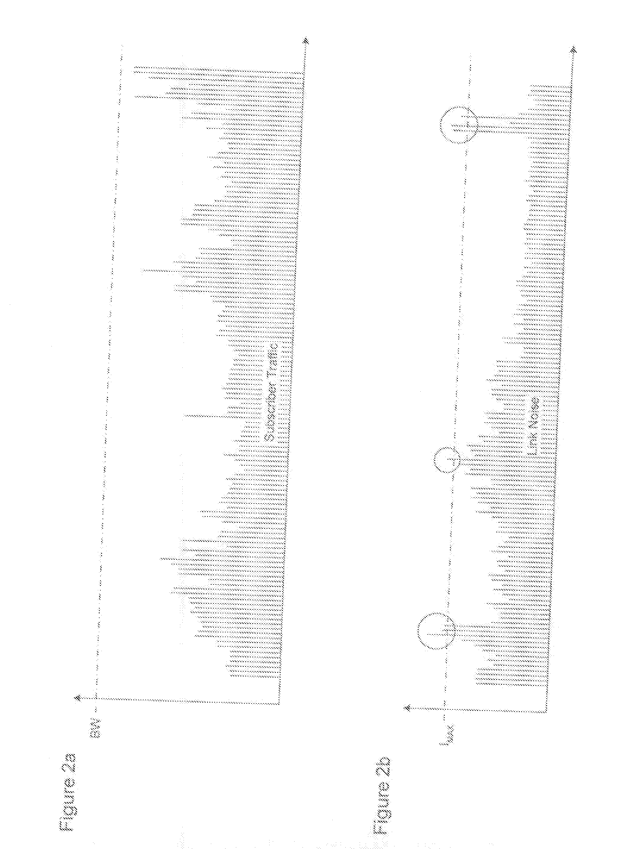
As a result, the instantaneous traffic load within a link of the optical network will frequently be significantly lower than the (noise margin limited) link bandwidth.
As the traffic load increases, the headroom decreases with an attendant rise in the risk of delayed or discarded packets, which is undesirable.
Clearly, the provisioning of such large amounts of headroom is expensive, because it requires that the network supplier lease significantly more link bandwidth than will actually be used, on average.

Method used


Image

  • Traffic driven variable bandwidth optical transmission
  • Traffic driven variable bandwidth optical transmission
  • Traffic driven variable bandwidth optical transmission

Examples


Embodiment Construction

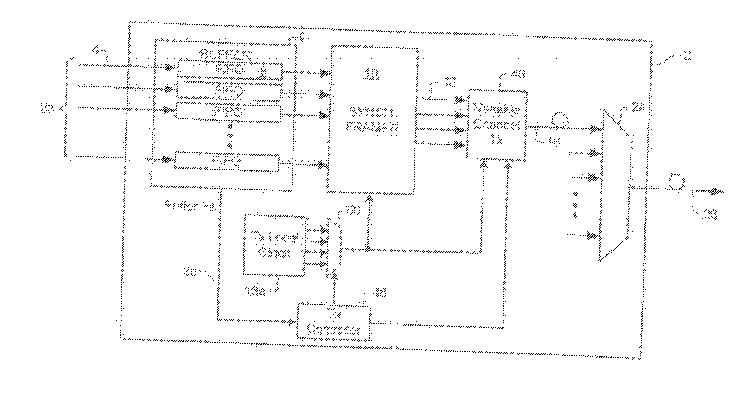
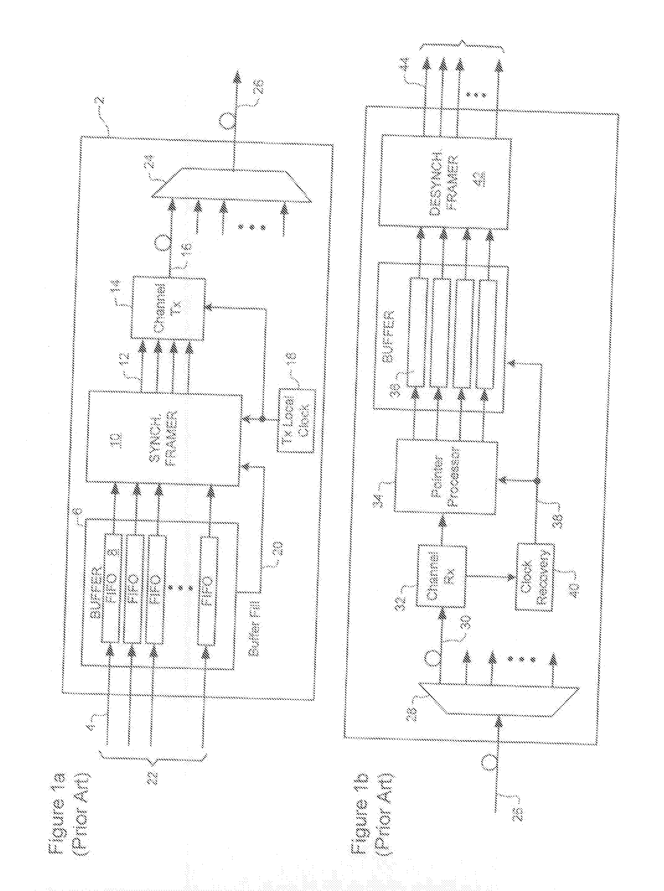
[0023]The present invention provides a method and apparatus for enabling traffic driven variable bandwidth optical transmission in an optical communications system. In order to facilitate understanding of the present invention, a brief description of prior art transmission systems is provided below with reference to FIGS. 1 and 2. Embodiments of the present invention will then be described with reference to FIGS. 3-6.

[0024]FIG. 1a is a block diagram schematically illustrating principal operations of a transmitting node 2 of an optical communications system. As shown in FIG. 1a, asynchronous subscriber signal traffic within multiple tributaries 4 is received by the node 2 and buffered in an elastic store 6. The traffic may comprise any arbitrary mix of signals, including Asynchronous Transfer Mode (ATM), Internet Protocol (IP), and Gigabit Ethernet traffic. Traffic within each tributary 4 is normally buffered in a respective First-In-First-Out (FIFO) buffer 8. A synchronising framer ...


PUM


Abstract

Link bandwidth is varied based on the subscriber traffic load. Varying the link bandwidth has the effect of varying the actual noise margin of the link (in an inverse elation), so that the noise margin will vary inversely with the traffic load. A beneficial result is that, because the noise margin is increased during “off-peak” traffic periods, rapidly varying and burst impairments can be absorbed without causing data loss. In effect, the respective probability distributions of error bursts and traffic load are separated. Data loss only becomes a significant risk when peaks in both distributions coincide. However, the probability of that event occurring is comparatively low. This enables a lower noise margin allocation during design of the link, which dramatically reduces the link cost.

Description

CROSS-REFERENCE TO RELATED APPLICATIONS[0001]This application is a continuation of application Ser. No. 10 / 436,129, filed May 13, 2003, now pending. The patent application identified above is incorporated here by reference in its entirety to provide continuity of disclosure.MICROFICHE APPENDIX[0002]Not Applicable.TECHNICAL FIELD[0003]The present invention relates to optical transmission systems, and in particular to traffic driven variable bandwidth optical transmission in an optical communications network.BACKGROUND OF THE INVENTION[0004]It is well known that the bandwidth of an optical communication link is limited by the noise margin required to ensure reliable communication. Typically, the noise margin, is measured in terms of a signal-to-noise ratio at the receiver end of a link. In some cases, the optical signal-to-noise ratio (OSNR) is directly measured at the receiver. In other cases, signal parameters such as the eye opening, or bit error rate (BER) detected at the receiver...

Claims


Application Information

Patent Timeline
Patent Type & Authority Applications(United States)
IPC IPC(8): H04B17/00
CPCH04J3/0605H04J3/0623H04J3/14H04L1/0017H04J3/1617H04L1/0002H04J3/1611
Inventor ROBERTS, KIM B.CHIABAUT, JEROME
Owner CIENA
Learn More