
Cup system with removable insulated liner

a technology of insulated liner and cup, which is applied in the direction of sealing, liquid handling, caps, etc., can solve the problems of high scrap rate, long manufacturing cycle, and inaccessible cleaning of contaminated trappings

Inactive Publication Date: 2012-09-06
NUK USA
View PDF5 Cites 2 Cited by
  • Summary
  • Abstract
  • Description
  • Claims
  • Application Information

AI Technical Summary

Benefits of technology

[0005]Mechanically bonded insulated cups have tight process parameters to avoid undesirable bonds, such as flash or gaps in the bonded junction between the liner and outer cup body. Tight process parameters lead to high scrap rates and longer manufacturing cycles. With a removable liner, this step may be eliminated in the manufacturing process for an insulated cup.
[0006]Insulated cups on the market are produced in high volumes. It is likely that while using an insulated cup, the user will come across an identical insulated cup. An insulated cup with a removable liner can be customized by the user, by inserting a picture or art work in between the liner and outer cup body. In one embodiment, the disclosed cup system allows for the placement of a picture or art work in between the liner and the outer cup body. To view the picture or artwork, the outer cup can be made from a transparent material and the liner can be made from an opaque or transparent material, such as pigmented plastics or polymers. The outer cup and liner can be made from materials capable of holding both hot and cold liquids, such that very hot liquids, such as boiling water or frozen water will not damage the materials. The material for the liner or outer cup body could be plastic or metal.
[0009]In one embodiment, the insulated cup provides the ability of cleaning all the surfaces of all the cup components. The parts can be disassembled for access to clean all surfaces.

Problems solved by technology

The trapped contaminates can be inaccessible to clean.
Also, if the mechanical bond fails, contaminates can pass into the air compartment in between the liner and outer cup body.
With the liner bonded to the outer cup body, there is no way to clean in between the two parts.
Tight process parameters lead to high scrap rates and longer manufacturing cycles.

Method used


Image

  • Cup system with removable insulated liner
  • Cup system with removable insulated liner
  • Cup system with removable insulated liner

Examples


Embodiment Construction

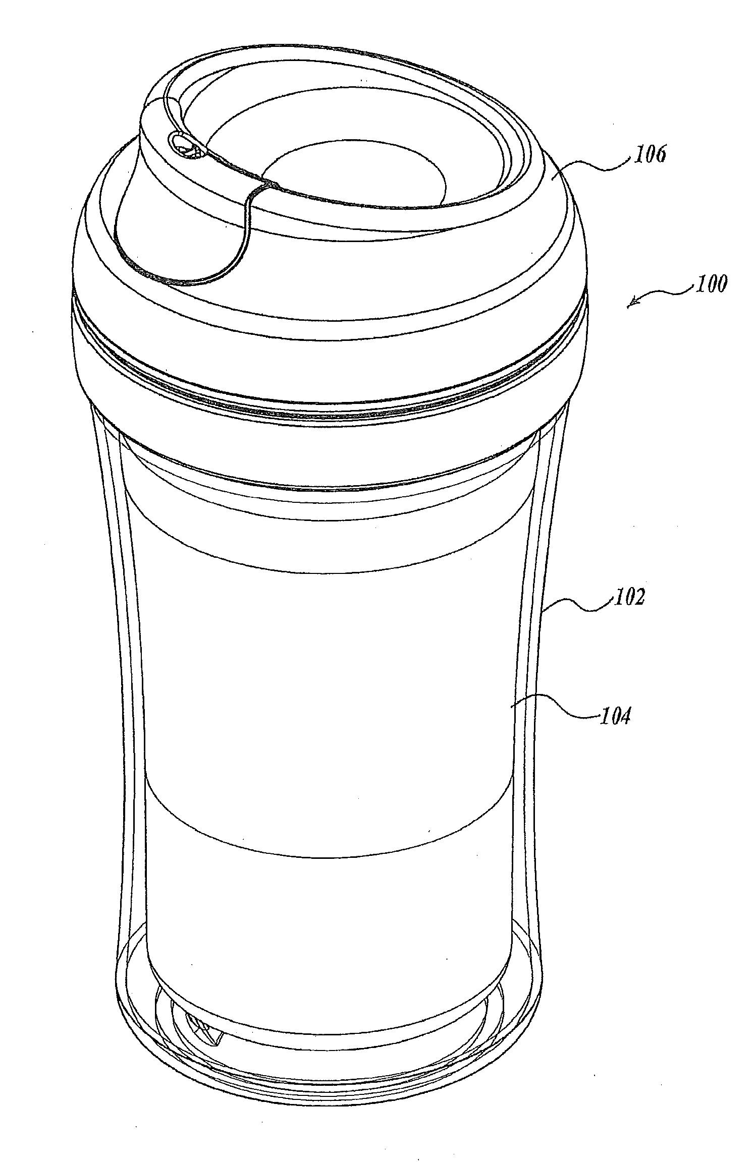
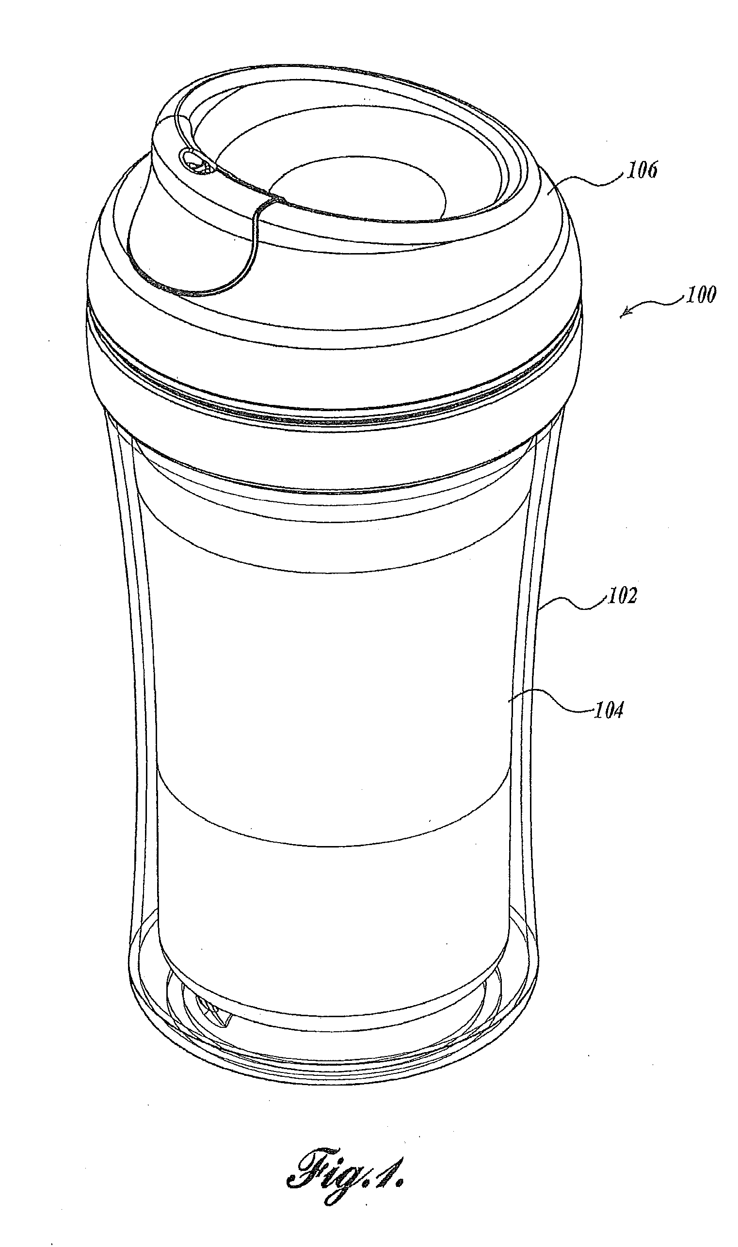
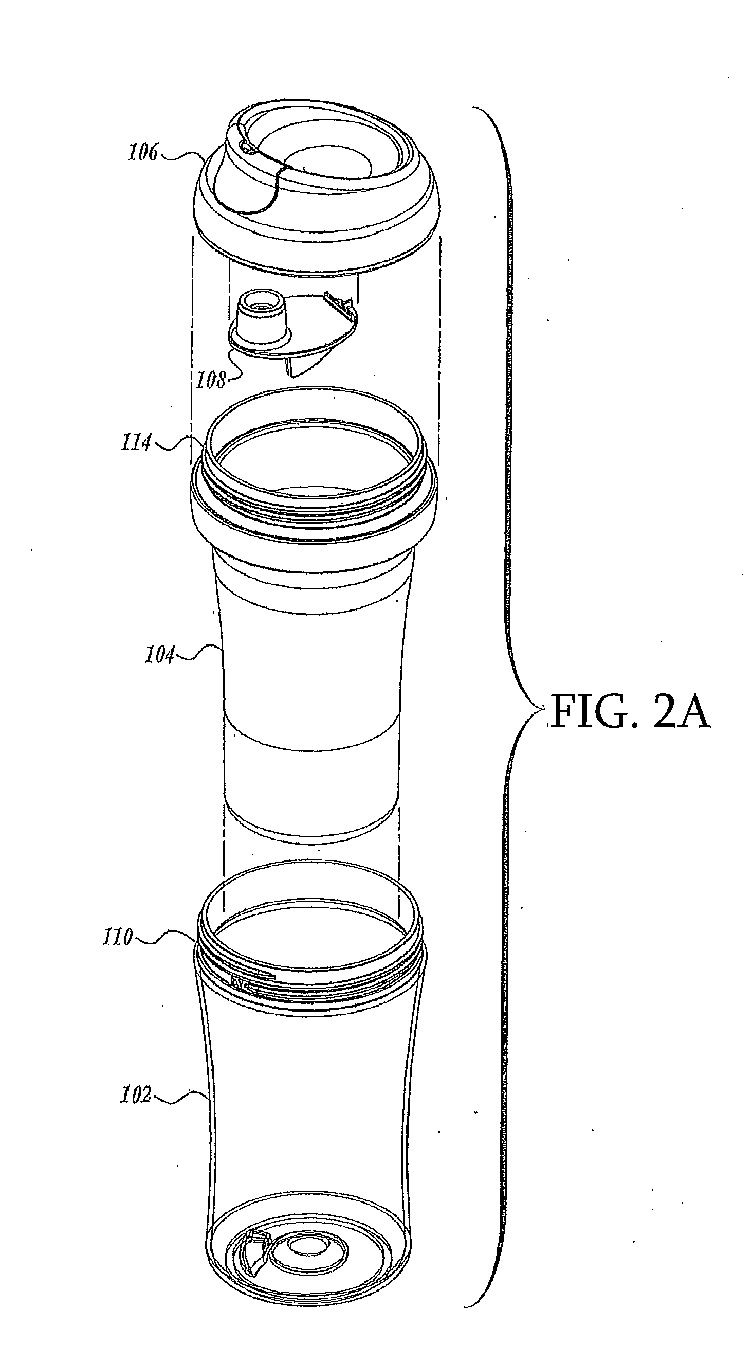
[0037]FIG. 1 is an illustration of a cup system 100 including an outer cup 102, an inner liner 104 and a lid 106. The outer cup 102 is formed from a cylindrical-shaped body having a closed end on the bottom and an open end on top to provide a container for liquids and / or the liner 104. The cup system 100 includes a removable liner 104. The liner 104 can be, provided for insulation in which case the liner 104 can hold the liquid. Alternatively, the liner 104 can be omitted in an alternative configuration of the clip system 100. The liner 104 is formed from a cylindrical shape having a closed bottom and an open top. The dimensions, such as the diameter, of the liner 104 may be smaller than the dimensions of the outer cup 102 so that the liner 104 may be placed within the cup 102 to provide a space between the liner 104 and cup 102. The cup system 100 includes a lid 106. The lid top surface if depressed in a concave manner, while the lid 106 lower surface includes a valve 108, which wi...


PUM

PropertyMeasurementUnit
diametersaaaaaaaaaa
insulating spaceaaaaaaaaaa
temperatureaaaaaaaaaa

Abstract

A cup system including a lid, a liner, an outer cup, and an optional valve. The liner includes first and second mating surfaces. The liner first mating surface is selectively attachable to a corresponding mating surface associated with the outer cup and the liner second mating surface is selectively attachable to a corresponding mating surface associated with the lid. The mating surface of the lid is also selectively attachable to the mating surface of the outer cup such that present cup can be utilized as either an insulated or a non-insulated cup. The optional valve assembles to the lid by pressing the boss of the valve into a valve receiver associated with the lid.

Description

CROSS-REFERENCE[0001]This application claims the benefit of and priority to U.S. Provisional Patent Application Ser. No. 61 / 421,534, filed Dec. 9, 2010, entitled CUP SYSTEM WITH REMOVABLE INSULATED LINER, which application is hereby incorporated by reference to the extent permitted by law.BACKGROUND OF INVENTION[0002]Cups intended to hold hot and cold liquids are generally insulated to maintain the temperature of the liquid for as long as possible. Spill-proof cups have also become ubiquitous. Spill-proof cups are used by almost everyone from toddlers (using the “sippy” cups) to adults and everyone in between engaging in physical activities. Spill-proof cups may have a lid with an opening that can be opened or closed with a mechanical closure. These closures can be made according to different designs. For toddlers, the sippy cups may include a valve that requires the toddler to create suction to draw the liquid out of the cup. The objective of spill-proof cups is to retain liquid wi...

Claims


Application Information

Patent Timeline
Patent Type & Authority Applications(United States)
IPC IPC(8): B65D51/00B65D53/00B23P19/04B65D41/04
CPCY10T29/49826A47G19/2272
Inventor GODFREY, ROBERT J.GATES, RICHARD H.ALBRECHT, BRIAN M.
Owner NUK USA
Learn More