Tomosynthesis mammography system with enlarged field of view

a mammography and enlarged field technology, applied in the field of tomosynthesis system, can solve the problems of poor lateral resolution, poor spatial image resolution, and inability to accurately represent 3d information in a 2d plane, and achieve the effect of improving patient comfort, high spatial image resolution, and large field of view

Inactive Publication Date: 2012-09-06
KONINKLIJKE PHILIPS ELECTRONICS NV
View PDF4 Cites 21 Cited by
  • Summary
  • Abstract
  • Description
  • Claims
  • Application Information

AI Technical Summary

Benefits of technology

[0006]There may be a need for an improved tomosynthesis mammography system which enables high spatial image resolution and / or a large field of view while preferably providing improved patient comfort.
[0008]A gist of the suggested tomosynthesis system may be seen as based on the following findings and ideas: In conventional digital breast tomosynthesis systems, while an X-ray source is moved along an arcuate path in order to irradiate an object to be observed from a plurality of tomographic angles, the X-ray detector is conventionally fixed in space. While this may allow for a simple moving mechanism which only has to move the X-ray source, a resulting three-dimensional field of view may be reduced when compared to normal screening mode mammography imaging. Furthermore, due to the X-ray detector being fixed, an X-ray beam from the X-ray source impinges onto the X-ray detector perpendicular only for a 0°-position of the X-ray source. At any other tomographic angles α≠0°, the X-ray beam will impinge onto the X-ray detector's surface under the corresponding angle α possibly resulting in the fact that not all X-rays may impinge onto the detection surface and may be detected by the detector. This may limit a possible range of tomographic angles to less than 25° (α≦25°).
[0020]Furthermore, a grid moving mechanism may be provided for moving the anti-scatter-grid parallel to the detection surface of the X-ray detector. Such movement of the anti-scatter-grid may avoid the formation of stripes within the acquired X-ray image. Typically, a linear movement may be in a range in the order of 2 cm. When the anti-scatter-grid is in an extreme position, it may be stopped and moved in the reverse direction.
[0021]According to another embodiment of the proposed tomosynthesis system, the moving mechanism is further adapted to move the detector such as to increase the distance (SID) between the X-ray source and the detector while an orientation of the detector remains fixed. In other words, additional to a first motion mode as described above in which the X-ray detector is moved in a pivoting motion in order to be always oriented towards the X-ray source, the moving mechanism also enables a second motion mode in which only the distance between the X-ray source and the detector is varied while the X-ray detector is not rotated / pivoted. Such possibility of varying the source-detector distance SID may enable a suitable magnification of the acquired X-ray image so that spatial resolution and DQE may be improved for example when acquiring images of a small breast. In such application, the provision of an anti-scatter grid may not be desired as the anti-scatter grid is usually optimized for one specific source-detector distance SID. Accordingly, the anti-scatter grid may be displaced into the parking position outside the beam path.
[0022]With the proposed tomosynthesis system, the X-ray source and the X-ray detector may be adapted to acquire X-ray images within a range of tomographic angles of more than + / −25°, for example more than + / −45°, preferably up to + / −60°. Such increased acquisition range may be mainly due to the fact that the X-ray detector is always oriented towards the X-ray source. Accordingly, even at high tomographic angles, no significant image distortion may occur. Furthermore, even at such high tomographic angles, an anti-scatter-grid may be used in order to improve a signal-to-noise ratio
[0023]With the proposed tomosynthesis mammography system, tomographic angles larger than 45° may be feasible, leading to better depth resolution combined with high 2D-sharpness. The proposed tomosynthesis system is compatible with conventional geometries and allows for both, regular screening mode and tomosynthesis mode. Furthermore, also stereotactic (guided) biopsy may be possible. Particularly for heavy breasts, a better contrast resolution may be obtained due to the possible use of an anti-scatter-grid. Furthermore, for small breasts, a variable source-detector distance may allow to use magnification techniques which also may lead to improved image quality.

Problems solved by technology

However, planar mammography is inherently limited to representing 3D information in a 2D plane.
Therefore, an X-ray sensitive layer of the detector has to be typically thicker, leading to a worse lateral resolution.
Typically a contrast agent is injected for the examination, so this modality may be not well suited for screening examinations.

Method used


Image

  • Tomosynthesis mammography system with enlarged field of view
  • Tomosynthesis mammography system with enlarged field of view
  • Tomosynthesis mammography system with enlarged field of view

Examples


Embodiment Construction

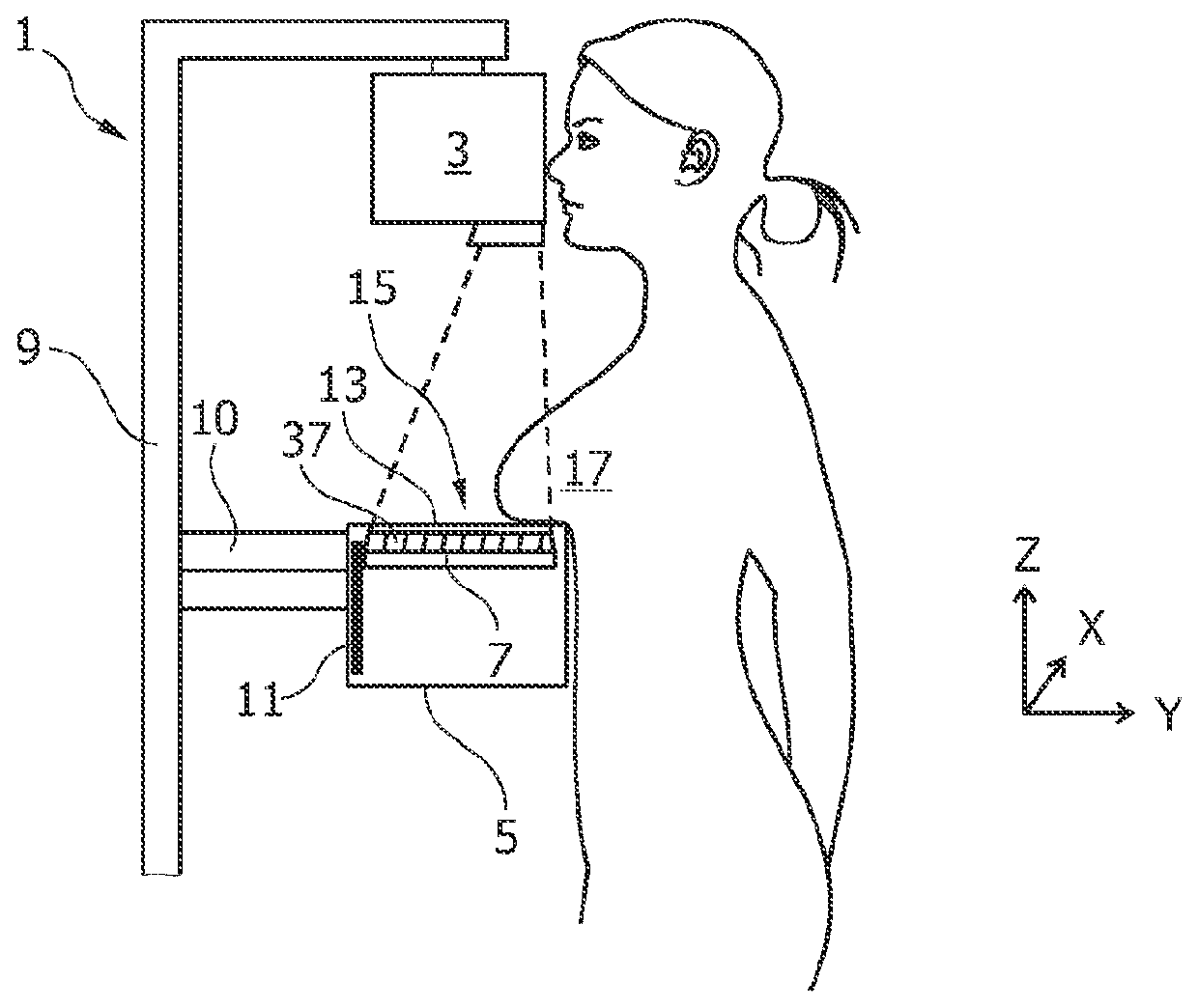
[0038]FIG. 1 shows a side view of a tomosynthesis mammography system 1 according to an embodiment of the present invention. An X-ray source 3 and a housing 5 comprising an X-ray detector 7 are attached to a supporting frame 9. An upper surface 13 of the housing 5 acts as a support arrangement 15 for supporting the female breast 17 to be examined during the operation of the tomosynthesis system 1. The housing 5 is substantially larger, for example by a factor 1.5 to 5, in its x-direction and its z-direction than the X-ray detector 7 accommodated therein. For example, the housing may be up to three times as large as the X-ray detector 7 in the x-direction and up to 5 times as large in the z-direction. Accordingly, the X-ray detector 7 may be arranged within the housing 5 at different locations and in different orientations. The housing 5 also comprises a moving mechanism 11 which is adapted to move the detector 7 along a pivoting motion path. Furthermore, as will be described further ...


PUM


Abstract

A tomosynthesis system for acquiring a three-dimensional image of an object such as a mammography image of a female breast is proposed. The tomosynthesis system (1) comprises an X-ray source (3), an X-ray detector (7), a support arrangement (15) and a moving mechanism (11). The X-ray source (3) and the X-ray detector (7) are adapted for acquiring a plurality of X-ray images while irradiating the object (17) with an X-ray beam (21) from a plurality of tomographic angles α. The moving mechanism (11) is adapted to pivot the X-ray detector (7) in positions such that for each tomographic angle α a detection surface (25) of the X-ray detector (7) is oriented to be substantially perpendicular to the X-ray beam (21). The moving mechanism (11) is adapted to move the X-ray detector (7) in positions such that a distance between the X-ray source (3) and the detector (7) is increased with increasing tomographic angle a thereby enabling that the X-ray detector (7) remains within an enlarged housing (5) during an entire tomographic image acquisition procedure.

Description

FIELD OF THE INVENTION[0001]The present invention relates to a tomosynthesis system for generating a three-dimensional image of an object such as a three-dimensional mammography image of a female breast.BACKGROUND OF THE INVENTION[0002]In order to detect and analyze breast cancer, various mammography systems are known.[0003]In conventional mammography screening systems, the female breast is compressed between two plates and soft X-rays are transmitted through the compressed tissue before being detected by an X-ray detector. However, planar mammography is inherently limited to representing 3D information in a 2D plane. While high lateral resolution, i.e. in an x-y-plane, may be achieved, no depth resolution, i.e. in a z-direction, may be obtained.[0004]In order to also realize depth resolution and furthermore in order to relax the requirement of strongly compressing the breast during examination, tomosynthesis mammography systems, also referred to as digital breast tomosynthesis (DBT...

Claims


Application Information

Patent Timeline
Patent Type & Authority Applications(United States)
IPC IPC(8): A61B6/04A61B6/03
CPCA61B6/02A61B6/4291A61B6/588A61B6/502A61B6/025
Inventor MAACK, HANNS-INGO
Owner KONINKLIJKE PHILIPS ELECTRONICS NV
Why Eureka
Try Eureka