Eureka AIR delivers breakthrough ideas for toughest innovation challenges, trusted by R&D personnel around the world.

Leaf valve structure

Active Publication Date: 2012-09-13
KYB CORP +1
View PDF7 Cites 0 Cited by
  • Summary
  • Abstract
  • Description
  • Claims
  • Application Information

AI Technical Summary

Benefits of technology

[0007]When a smoothness of the valve seat is improved due to improvements in processing precision, the leaf valve adheres to the crown portion of the valve seat with a great surface adsorption force. Therefore, a greater amount of pressure than a normal cracking pressure may be required to lift the leaf valve adhered to the crown portion of the valve seat.
[0009]It is therefore an object of this invention to reduce the effect of a difference in a viscosity of a working fluid on a cracking pressure of a leaf.

Problems solved by technology

Sudden lifting of the leaf causes noise generation.
Further, variation in the cracking pressure of the leaf leads to variation in the damping force characteristic.

Method used


Image

  • Leaf valve structure
  • Leaf valve structure
  • Leaf valve structure

Examples


Embodiment Construction

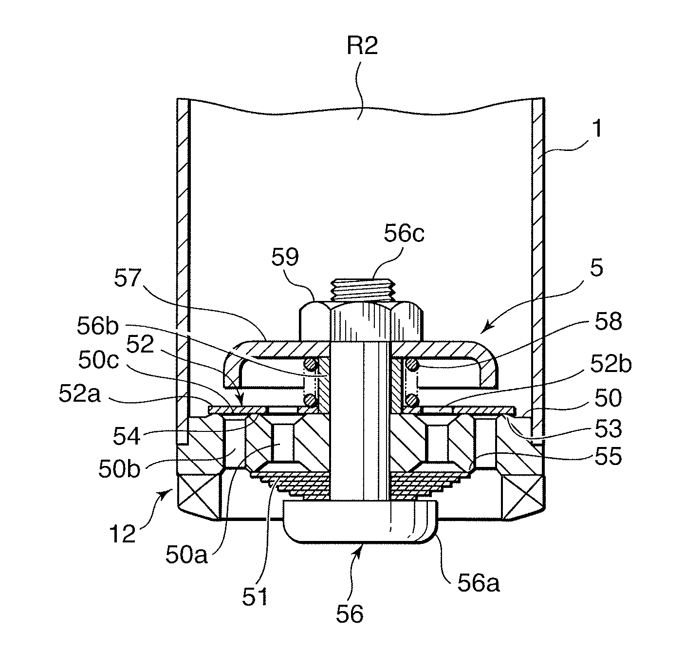
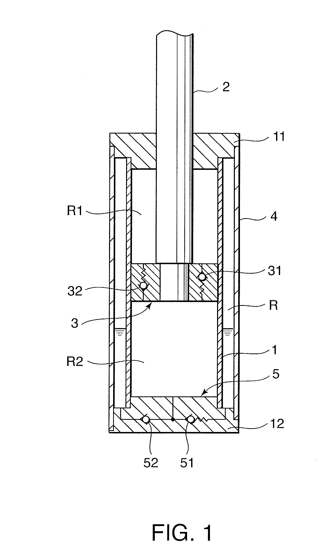
[0015]Referring to FIG. 1 of the drawings, a leaf valve structure according to this invention is applied to a base valve 5 of a hydraulic shock absorber that absorbs road surface vibration input into a vehicle, for example.

[0016]The hydraulic shock absorber includes a cylinder 1, a piston rod 2 inserted into the cylinder 1 from an axial direction to be free to slide, and a piston 3 fixed to a tip end of the piston rod 2 in order to slide along an inner periphery of the cylinder 1.

[0017]A piston rod side oil chamber R1 and an opposite side oil chamber R2 are defined by the piston 3 on an inner side the cylinder 1.

[0018]The cylinder 1 is housed inside an outer tube 4 coaxially therewith. One axial direction end of the outer tube 4 and the cylinder 1 is tightly sealed by a rod guide 11. Another axial direction end of the outer tube 4 and the cylinder 1 is tightly sealed by a bottom block 12. The piston rod 2 penetrates the rod guide 11 to be free to slide in the axial direction.

[0019]A...


PUM


Abstract

A leaf valve structure according to this invention comprises an annular valve seat, and a leaf that is seated on the valve seat under a predetermined elastic supporting force against a pressure of a working fluid on an inner side of the valve seat. A recessed depression portion having an opening portion on both an inner periphery of the valve seat and a seating surface of the leaf is formed in the valve seat, thereby creating a site where the pressure of the working fluid on the inner side of the valve seat can act more easily on a seating surface between the valve seat and the leaf valve. Accordingly, an effect of a surface adsorption force applied to the leaf valve by the valve seat on a cracking pressure can be suppressed, and as a result, the leaf valve can be lifted under a stable cracking pressure.

Description

FIELD OF THE INVENTION[0001]This invention relates to a damping valve for a hydraulic shock absorber.BACKGROUND OF THE INVENTION[0002]A hydraulic shock absorber that absorbs road surface vibration input into a vehicle includes a damping valve that damps vibration by applying resistance to a flow of working fluid. JP01-111840U, published by the Japan Patent Office in 1996, proposes a damping valve structure for reducing an effect of a viscosity of the working fluid on a generated damping force.[0003]The damping valve includes a main leaf valve seated on a valve seat and a sub-leaf valve seated on a hole portion formed in the main leaf valve. By setting a valve opening pressure of the sub-leaf valve to be lower than a valve opening pressure of the main leaf valve, working oil flows through the sub-leaf valve when a shock absorber strokes at a low speed, and when the shock absorber strokes at a high speed, the main leaf valve opens.[0004]By constructing the damping valve in this manner...

Claims


Application Information

Patent Timeline
IPC IPC(8): F16F9/348F16F9/52F16K17/08
CPCF16F9/348F16F2230/36F16F2222/10Y10T137/7858Y10T137/7932
Inventor YAMADA, HIDEKIMURAKAMI, TOMOHARUOIKAWA, TADASHIAMINO, TOMOHITONOMURA, YOSHINORI
Owner KYB CORP
Why Eureka
Eureka Blog
Learn More