

Handheld electric mixer
- Summary
- Abstract
- Description
- Claims
- Application Information
AI Technical Summary
Problems solved by technology
Method used
Image

Examples
Embodiment Construction
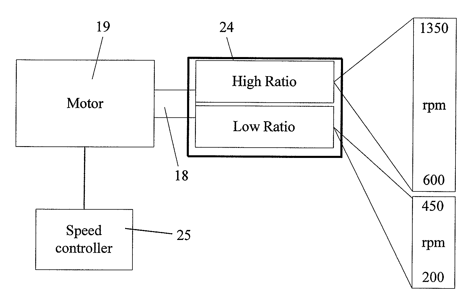
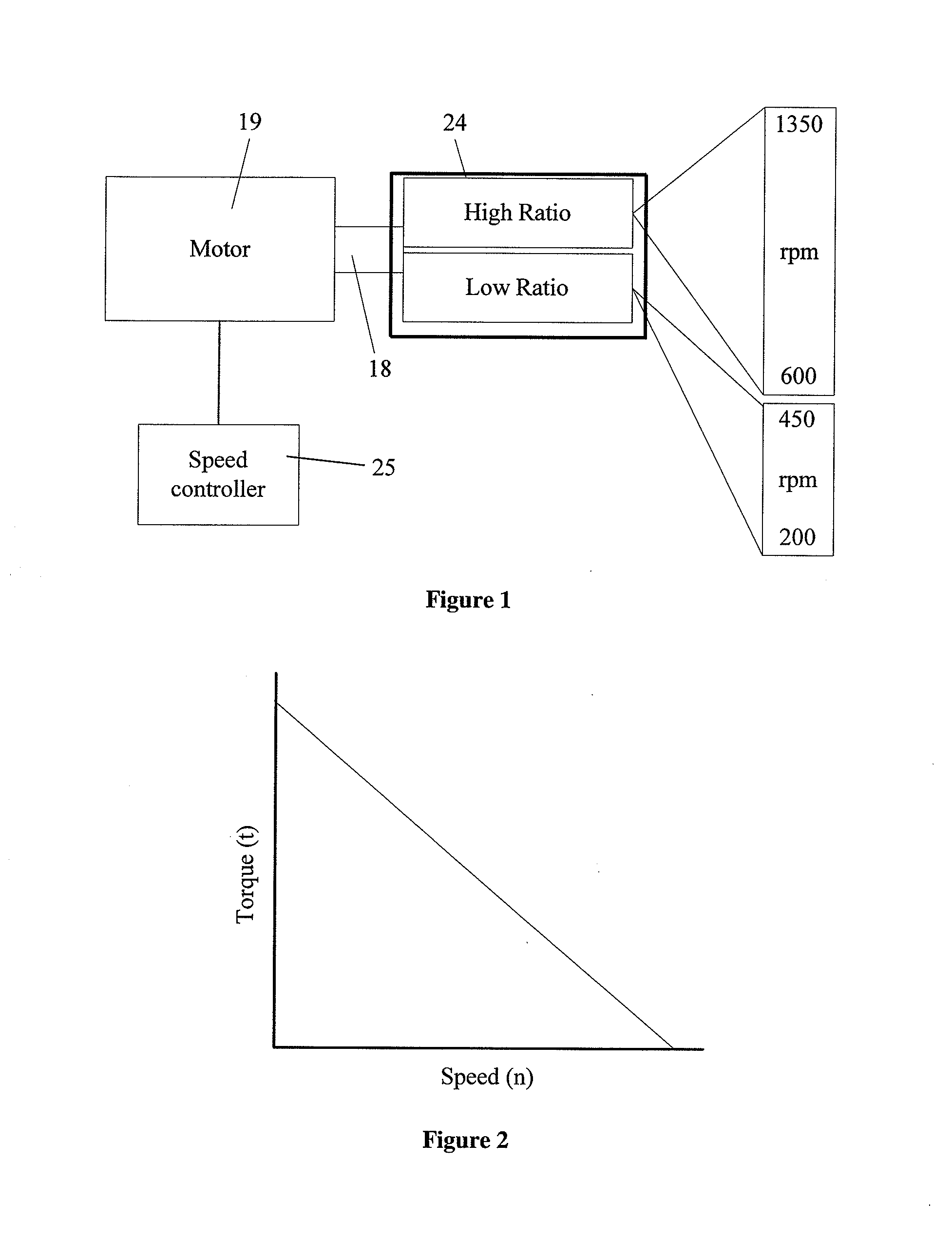
[0020]A handheld electric mixer according to the present invention utilises both electronic and mechanical speed control means to provide greater speed and torque ranges than handheld electric mixers hitherto known in the art. Referring to FIGS. 1 and 2, the mixer is driven by a motor 19 having a rotational output shaft 18. Rotational speed of the motor 19 is controlled electronically by an electronic speed controller 25. A two-speed gear-box 24, having low and high gear ratios, receives torque from the output shaft 18 of the motor and transmits it to a pair of rotational output spindles 23. The combination of electronic speed controller 25 and two-speed gear-box 24 provides the chief or cook with a larger range of torque and speed for mixing, blending, beating or otherwise acting upon a food item or recipe constituents. As will be apparent to the skilled addressee, for any give power output torque is inversely proportional to speed (i.e. t=1 / n, where t is torque and n is rotational...
PUM
 Abstract
Description
Claims
Application Information