Squirrel-cage rotor of induction motor and production method thereof wherein end ring is brazed with bar

Inactive Publication Date: 2012-09-13
FANUC LTD
View PDF7 Cites 11 Cited by
  • Summary
  • Abstract
  • Description
  • Claims
  • Application Information

AI Technical Summary

Benefits of technology

[0010]Therefore, an object of the present invention is to provide a squirrel-cage rotor of an induction motor and a production method thereof,

Problems solved by technology

The melting point of copper or copper alloy is higher than that of aluminum, and thus it is difficult to utilize a die-cast process or the like for producing the motor, since the rotor core is a magnetic steel sheet that may be affecte

Method used


Image

  • Squirrel-cage rotor of induction motor and production method thereof wherein end ring is brazed with bar
  • Squirrel-cage rotor of induction motor and production method thereof wherein end ring is brazed with bar
  • Squirrel-cage rotor of induction motor and production method thereof wherein end ring is brazed with bar

Examples


Example

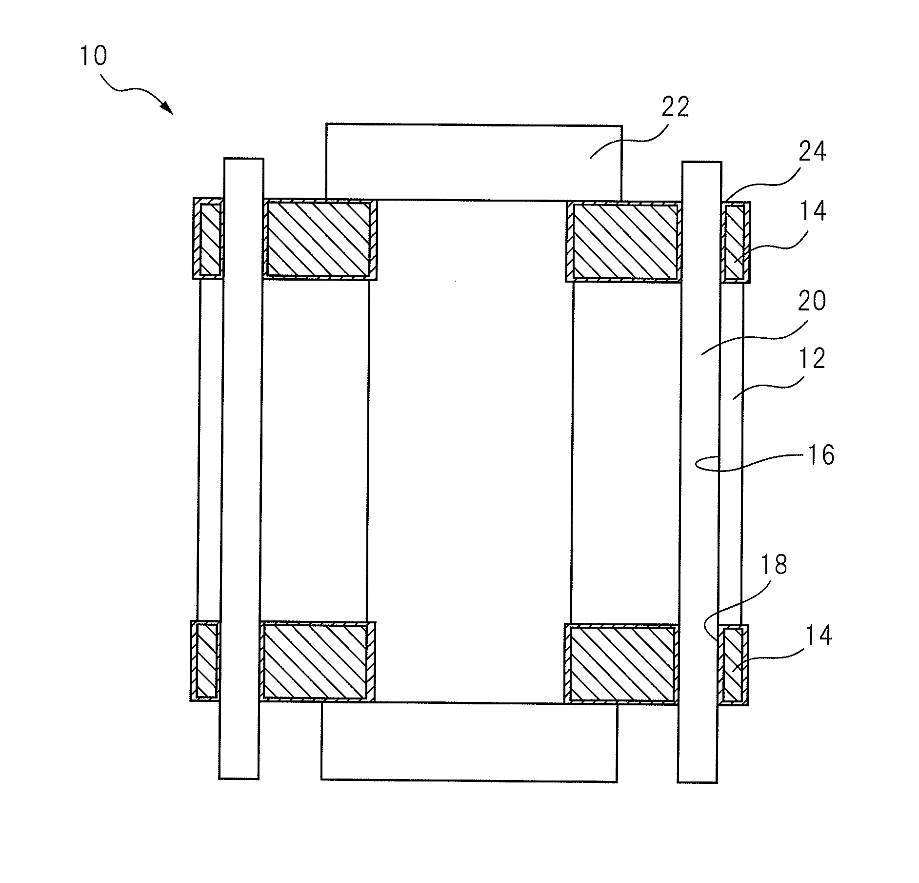
[0021]FIG. 1 shows a schematic configuration of a squirrel-cage rotor 10 according to one embodiment of the invention, wherein a sectional view along a rotation axis of the rotor is illustrated. Squirrel-cage rotor 10 has a rotor core 12 made from a silicon steel sheet or plate, and an end ring 14 made from pure copper or copper alloy and positioned at both ends of rotor core 12 in relation to a rotation axis of the rotor core. Rotor 10 further has at least one conductive rotor bar 20 made from pure copper or copper alloy and configured to be inserted into a though hole 16 formed in rotor core 12 and a through slot 18 formed in end ring 14, and a fixture 22 configured to fix the above components or the rotor.

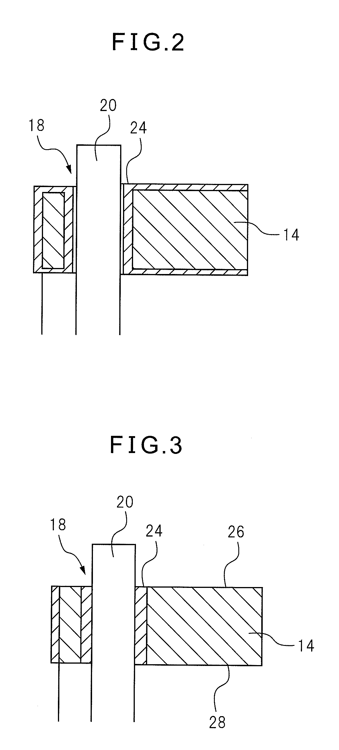
[0022]The shape of through slot 18 of end ring 14 is generally complementary to the outer shape of conductive bar 20. In the illustrated embodiment, each of an inner surface of through slot 18 and an outer surface of conductive bar 20 is a cylindrical surface. However, through s...


PUM


Abstract

A squirrel-cage rotor of an induction motor and a production method thereof, wherein locating of the brazing material is not necessary in order to reduce manhours for brazing, and a bar is easily connected to an end ring. Before assembling a rotor core, a silver plated layer is formed on at least one of an end ring and a conductive bar. In order to melt the silver plated layer, the rotor is heated to a temperature which is equal to or larger than the melting point of the silver plated layer. The melted layer functions as a brazing material, whereby the end ring and the conductive bar are connected.

Description

BACKGROUND OF THE INVENTION[0001]1. Field of the Invention[0002]The present invention relates to a squirrel-cage rotor of an induction motor and a production method thereof, wherein an end ring is brazed with a bar.[0003]2. Description of the Related Art[0004]Generally, a squirrel-cage rotor of an induction motor is constituted by major three components, i.e., a laminated core produced by punching a magnetic steel sheet, slot-shaped conductive bodies positioned in a plurality of slots formed in the core, and an end ring for short-circuiting the conductive bodies at both ends of the rotor. Usually, to reduce cost the slot-shaped conductive bodies and the end ring are integrally formed with the rotor core, by die-cast molding of aluminum.[0005]In recent years, it is desired to reduce heat generated by a motor, and then copper or copper alloy, having lower electric resistance than aluminum, may be used as the metal that forms a conductive portion of a rotor of the motor. The melting po...

Claims


Application Information

Patent Timeline
IPC IPC(8): H02K17/16H02K15/02
CPCH02K15/0012Y10T29/49012H02K17/165
Inventor HAYAHI, DAISUKEFUKUDA, MASAMOTOMAEDA, HISASHI
Owner FANUC LTD
Why Eureka
Try Eureka