
Indirect fed antenna

a technology of indirect feeding and antennas, applied in the direction of elongated active element feed, resonant antennas, radiating element structural forms, etc., can solve the problems of difficult optimization, damage to feed or transmitter, and limited antenna volume, so as to improve bandwidth.

Inactive Publication Date: 2012-09-13
MOLEX INC
View PDF5 Cites 26 Cited by
  • Summary
  • Abstract
  • Description
  • Claims
  • Application Information

AI Technical Summary

Benefits of technology

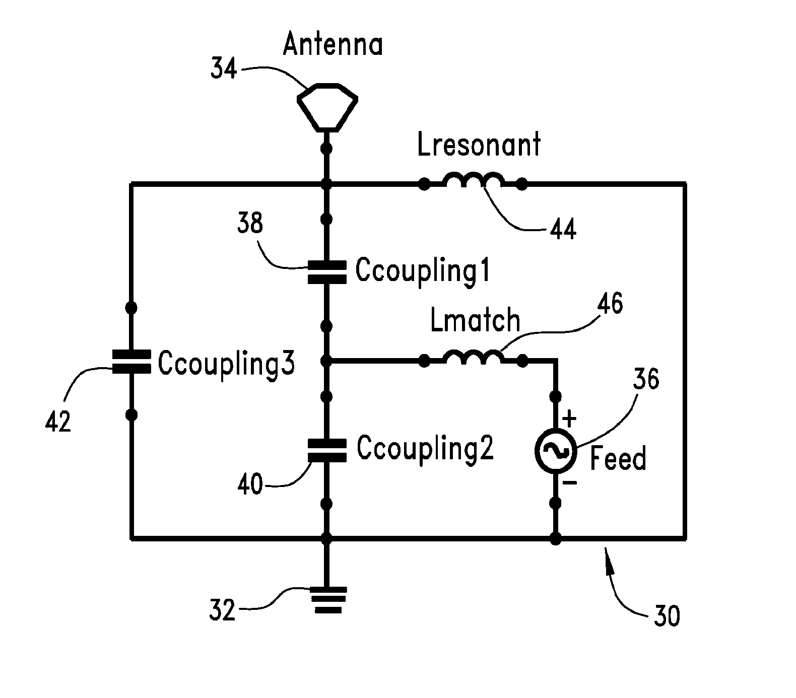
[0005]An embodiment of an antenna system includes a resonant element that is electrically coupled to a ground plane. The resonant element is also configured to be capacitively coupled to a coupler, and the coupler is electrically coupled to a feed which is configured to be electrically coupled to a transmitter (which may be a transceiver). Thus, the resonant element is indirectly coupled to the feed. When the coupler receives a signal from the transmitter via the feed, the capacitive coupling between the coupler element and the resonant element, in combination with the capacitive coupling between the coupler and the ground plane, helps provides an antenna system with improved bandwidth versus a system that used a comparably sized resonating element and a direct feed.

Problems solved by technology

One area that has proven challenging to optimize in this regard is the antenna.
Particularly for antennas that transmit signals it is beneficial to have sufficient impendence bandwidth because transmission outside an appropriate frequency range can cause increases in reflected power, which can damage the feed or transmitter.
However, the volume of space available for the antenna is often limited.

Method used


Image

  • Indirect fed antenna
  • Indirect fed antenna
  • Indirect fed antenna

Examples


first embodiment

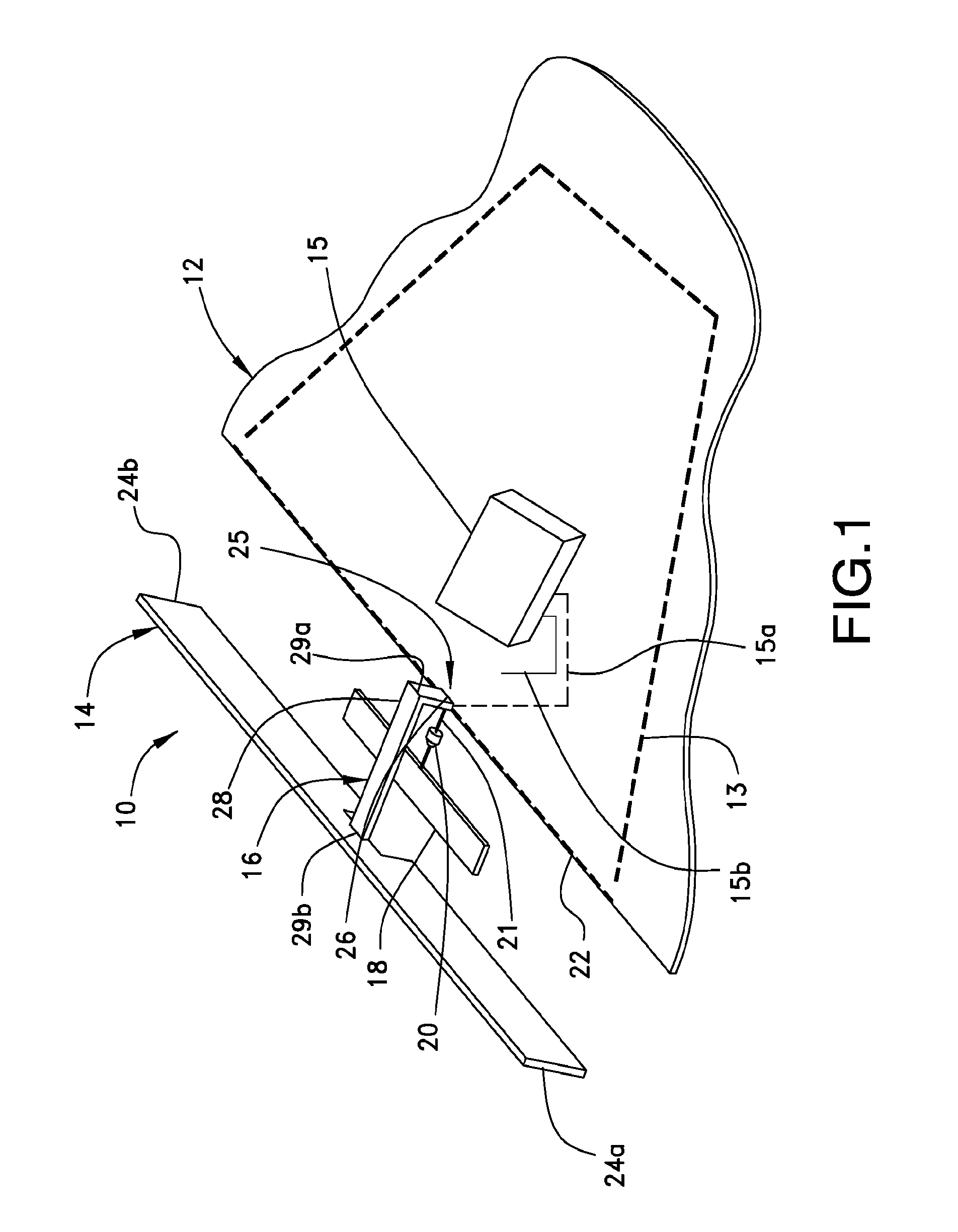
[0033]A first embodiment is shown in FIG. 1 and is a high impedance slot fed antenna (HISFA) 10. The HISFA is provided in connection with a circuit board 12 which provides a ground plane 13 and a transceiver 15. The HISFA 10 includes a resonant element 14 connected to the ground plane 13 through a ground arm 16 and a coupler 18 spaced from both the circuit board 12 and the resonant element 14. A feed 20 is electrically connected to the transceiver 15 via transmission line 15a and the feed 20 may include a circuit element 21 (which may be one or more elements that allow for better impedance matching between the transceiver 15 and the antenna 10) and the feed 20 provides the input that allows the antenna 10 to transmit signals.

[0034]A portion of the circuit board 12 is shown in FIG. 1. The dimensions of the circuit board 12 and the location and configuration of the ground plane 13 (which is shown in phantom line) and transceiver 15 (which can be coupled to the ground plane 13 via tran...

embodiment 100

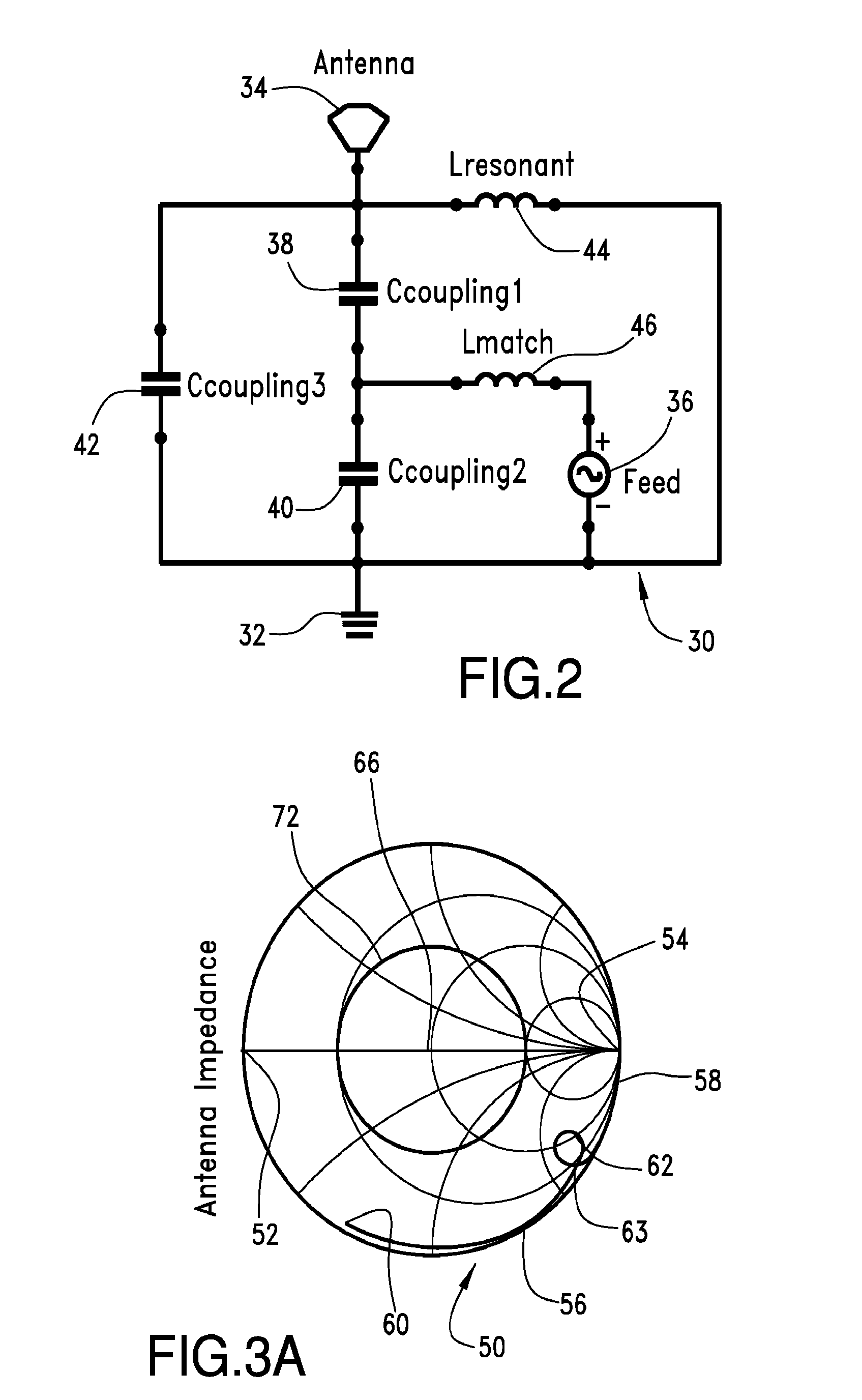
[0067]A circuit 160 representative of the antenna embodiment 100 of the LISFA of FIG. 5A is illustrated in FIG. 6A. The circuit 160 includes a ground plane 162 representative of the ground plane 113 of the circuit board 102; a resonant element 164 representative of the resonant element 104; and a feed 166 representative of the feed 106. The representative circuit 160 also includes the elements Ccoupling 168, Lresonant 170, Lmatch 172, Lreturn 174, Cslot 176 and Lslot 178.

[0068]Ccoupling 168 represents capacitive coupling which exists in the LISFA 100 between the resonant element 104, 164 and the ground plane 113, 162. Resonant inductance, Lresonant 170, provides impedance between the ground plane 113, 162 and the resonant element 104, 164. Although not illustrated in FIG. 5A, the resonant inductance 170 can be one or more discrete elements which can be selected and used to force the resonant element 104 into resonance at a desired frequency.

[0069]Impedance matching component, Lmatch...


PUM


Abstract

An indirect-fed antenna system is disclosed. In an embodiment, a coupler is electrically coupled to a feed. The coupler capacitively couples to a resonating element and the resonating element is electrically coupled to a ground plane. The system allows for improved band-width and also allows for an antenna design where the resonant frequency, the bandwidth of the antenna, the location of the curl on a Smith chart and the associated impendence matching network can be separately adjusted.

Description

[0001]This application claims priority to U.S. Provisional Application Ser. No. 61 / 240,644, filed on Sep. 8, 2009, to U.S. Provisional Application Ser. No. 61 / 255,609, filed Oct. 28, 2009 and to U.S. Provisional Application Ser. No. 61 / 319,514, filed Oct. Mar. 31, 2010, each of which is hereby incorporated by reference in its entirety.FIELD OF THE INVENTION[0002]This invention is generally directed to antennas and antenna feed arrangements suitable for use with wireless electronic devices.BACKGROUND OF THE INVENTION[0003]Modern devices suitable for receiving wireless signals have diverging requirements. One the one hand, there is constant pressure to reduce the size and cost of the device. On the other hand, there is a constant desire to improve performance. One area that has proven challenging to optimize in this regard is the antenna.[0004]Manufactures of devices that include antennas want the antennas to work effectively in a range of environmental conditions, while being small a...

Claims


Application Information

Patent Timeline
Patent Type & Authority Applications(United States)
IPC IPC(8): H01Q1/50H01Q1/38H01Q5/10
CPCH01Q9/30H01Q13/10H01Q9/42
Inventor JAGIELSKI, OLESVENDSEN, SIMON
Owner MOLEX INC
Learn More