Vehicle charge cable socket connector

a technology of charging cable and socket connector, which is applied in the direction of coupling device connection, coupling device details, connection contact member material, etc., can solve the problems of affecting the electrical conduction between the socket contact and the plug contact, affecting the electrical conduction of the socket, and promoting erosion of the contact surface, etc., to achieve high electrical connection reliability, and high electrical connection reliability

Inactive Publication Date: 2012-09-13
SMK CORP
View PDF31 Cites 20 Cited by
  • Summary
  • Abstract
  • Description
  • Claims
  • Application Information

AI Technical Summary

Benefits of technology

[0011]The present invention has been achieved in order to solve the foregoing problem. It is thus an object of the present invention to provide a vehicle charge cable socket connector which avoids the adverse effects of dust particles and rain drops entering the interior of a socket contact upon electrical contact, and maintains high electrical connection reliability for a long period even in outdoor use.
[0016]According to the invention set forth in claim 1, dust particles and rain drops that enter the interior of the socket contact can be let out through the through hole that extends from inside the socket contact to outside the housing. It is therefore possible to maintain high electrical connection reliability for a long period without adding dustproof or drip-proof members.
[0017]According to the invention set forth in claim 2, the elastic contact piece is covered with the contact cover, and the end annular part of the contact cover is in contact with the inner side of the end narrow-necked part of the contact accommodation part. Such a configuration can effectively prevent dust particles and rain drops from entering the contact accommodation part. Since no dust particles or rain drops reside in the contact accommodation part, it is possible to prevent dust particles and rain drops from returning to inside the elastic contact piece to affect the electrical contact. High electrical connection reliability can thus be maintained for an even longer period.
[0018]According to the invention set forth in claim 3, when the elastic contact piece is formed by splitting the end part of the socket contact, the split can be stopped up with the rib that is formed on the contact cover. With such a structure, dust particles and rain drops that enter the interior of the socket contact are guided into the through hole without being reserved in the split, whereby the socket contact is kept clean inside. High electrical connection reliability can thus be maintained for an even longer period.
[0019]According to the invention set forth in claim 4, the socket contact has a cylindrical bottom part, and the rotation of the socket contact with respect to the housing is restricted. The socket connector can thus be assembled so that the contact through hole and the housing through hole are opposed to each other without fail. Consequently, dust particles and rain drops that enter the interior of the socket contact can be smoothly let out.

Problems solved by technology

Dust particles can hinder electric conduction between socket contacts and plug contacts.
Rain drops can promote erosion of the contact surfaces on the socket contacts and plug contacts.
With such a method as disclosed in Japanese Patent No. 3195181, however, it is not possible to let out muddy water and the like that fail to be removed by the O ring and get into the socket contact when mating and unmating the charge cable.
The possibility of the foregoing problem has not been successfully dispelled yet.

Method used


Image

  • Vehicle charge cable socket connector
  • Vehicle charge cable socket connector
  • Vehicle charge cable socket connector

Examples


Embodiment Construction

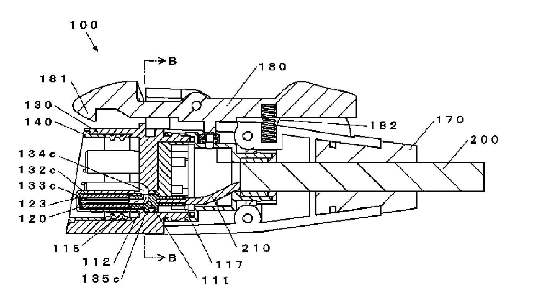
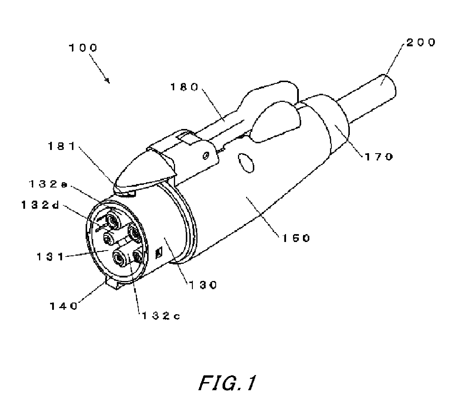
[0028]A vehicle charge cable socket connector 100 according to an embodiment of the present invention will be described below with reference to FIGS. 1 to 7. In the drawings, a charge cable 200 is shown only in part. The other end of the charge cable 200 is connected to a not-shown charger.

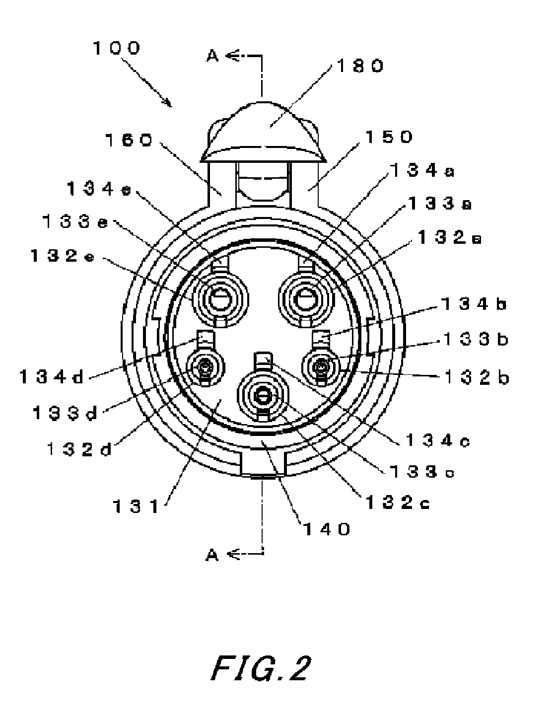
[0029]FIG. 1 shows the appearance of the vehicle charge cable socket connector 100 according to the embodiment of the present invention. The socket connector 100 is attached to an end of a charge cable 200 in a watertight manner via an elastic bushing 170. A cylindrical housing 130 is exposed in part at an end portion of the socket connector 100. The interior of the cylindrical end portion constitutes a plug connector accommodation part 131. The plug connector accommodation part 131 accommodates a plug connector 300 to be described later when the plug connector 300 is connected.

[0030]In the present embodiment, the body section extending from the plug connector accommodation part 131 to the busing ...


PUM


Abstract

Electrical connection reliability of a vehicle charge cable socket connector is maintained for a long period. Dust particles and rain drops that inevitably get into a socket contact can be let out through a contact through hole and a housing through hole that extend from inside the socket contact to outside a housing. Such a configuration can avoid adverse effects of dust particles and drain drops on electrical contact and maintain high connection reliability for a long period.

Description

CROSS REFERENCE TO RELATED APPLICATION[0001]The contents of the following Japanese patent application are incorporated herein by reference,[0002]NO. 2011-073487 filed on Mar. 10, 2011.BACKGROUND[0003]1. Technical Field[0004]The present invention relates to a charge cable connector for use in charging a vehicle on which a secondary battery is mounted, such as an electric vehicle.[0005]2. Description of the Related Art[0006]Nowadays, ecologically-friendly vehicles such as electric vehicles and plug-in hybrid vehicles are becoming prevalent that use a motor as their main source of driving force and on which a secondary battery is mounted as a means for supplying electric power to the motor. A typical method of charging such a vehicle-mounted secondary battery is to connect the vehicle and a predetermined charger with a charge cable and supply electric power from the charger to the vehicle for charging. Such a charging method requires the provision of connectors that detachably engage t...

Claims


Application Information

Patent Timeline
Patent Type & Authority Applications(United States)
IPC IPC(8): H01R4/60
CPCH01R13/111H01R2201/26H01R13/5227
Inventor KINOSHITA, KATSUHIRO
Owner SMK CORP
Why Eureka
Try Eureka