Dynamic dispersion detecting method and apparatus

a dynamic dispersion and detection method technology, applied in the field of communication technologies, can solve the problems of serious impact on system performance, inability to connect services, and increase the complexity of add/drop and switching channels at different nodes, so as to improve system residual dispersion detection accuracy, the effect of easy detection of peak electrical signal errors and high accuracy

Active Publication Date: 2012-09-13
HUAWEI TECH CO LTD
View PDF5 Cites 5 Cited by
  • Summary
  • Abstract
  • Description
  • Claims
  • Application Information

AI Technical Summary

Benefits of technology

[0024]As can be seen from the above technical solution, an optical signal is converted into an electrical signal, a peak electrical signal error is found, and then the residual dispersion value of the system is obtained according to the peak electrical signal error. Because the dispersion value related to the peak electrical signal error is the best residual dispersion value of the system, the best residual dispersion value of the system may be detected. Because the pulse broadening of the electrical signal error is narrow, the peak electrical signal error can be found more easily. When the best residual dispersion value is determined according to the electrical signal error, the accuracy is high and thus the precision of the system residual dispersion detection is increased. Further, as the detected best residual dispersion is used for dispersion compensation, the signal does not miss the best dispersion window of the system and the reliability is improved. Moreover, the tuning no longer needs to wait until the service is connected and error bits can be transmitted. Therefore, the service connection of the system is faster.

Problems solved by technology

In the future intelligent global communication network, the add / drop and switching of channels at different nodes will be more and more complex.
The residual dispersion value is likely to exceed the dispersion tolerance of the system and therefore seriously impacts the performance of the system.
Because TDC tuning and signal demodulation are performed simultaneously, it is the case that the demodulation of the signal has not been completed at the same time that the TDC is tuned within the proper dispersion window of the signal, so that the service cannot be connected and the best dispersion window is missed, and then the service is disconnected.
The tuning is slow and adds to the service connection time of the system.

Method used


Image

  • Dynamic dispersion detecting method and apparatus
  • Dynamic dispersion detecting method and apparatus
  • Dynamic dispersion detecting method and apparatus

Examples


Embodiment Construction

[0032]To illustrate the technical solution in the embodiments of the present invention or in the prior art more clearly, the following describes the accompanying drawings necessary for the description of the embodiments or the prior art briefly. Apparently, the embodiments described are only exemplary embodiments of the present invention and the present invention is not limited to such embodiments. Based on the embodiments herein, those skilled in the art can derive all of the other embodiments without creative efforts and such other embodiments all fall within the scope of the present invention.

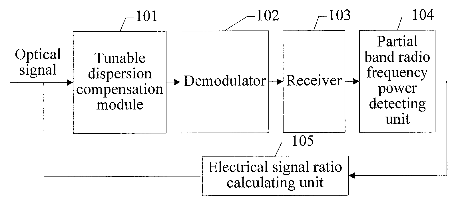
[0033]Dispersion detection techniques and compensation play a core role in a dynamic dispersion compensation system. The range and precision of dispersion detection directly decide the range and precision of the dynamic dispersion compensation system. The complexity of dispersion detection also directly decides the total cost of the compensation system. The dispersion tolerance of optical mo...


PUM


Abstract

A dynamic dispersion detecting method and apparatus are disclosed. The apparatus includes a tunable dispersion compensation module (101), a demodulator (102), a receiver (103), a partial band radio frequency power detecting unit (104), and an electrical signal ratio calculating unit (105). The method includes: demodulating a phase of a received optical signal; converting the demodulated optical signal into an electrical signal; sampling radio frequency power of the electrical signal to obtain an radio frequency signal; obtaining an electrical signal ratio of the radio frequency signal; and comparing a value of a currently detected electrical signal ratio with the values of the previously detected electrical signal ratios, tuning a dispersion compensation value according to a comparison result to find a peak electrical signal ratio, and obtaining a residual dispersion value of a system according to the peak electrical signal ratio.

Description

CROSS-REFERENCE TO RELATED APPLICATIONS[0001]This application is a continuation of International Patent Application No. PCT / CN2010 / 078608, filed on Nov. 10, 2010, which claims priority to Chinese Patent Application No. 200910222614.3, filed on Nov. 19, 2009, both of which are hereby incorporated by reference in their entireties.FIELD OF THE INVENTION[0002]The present invention relates to the field of communication technologies, and in particular, to a dynamic dispersion detecting method and apparatus.BACKGROUND OF THE INVENTION[0003]In an optical communication system, dispersion tolerance is in inverse proportion to the bit rate. As the bit rate increases, the dispersion tolerance of the system decreases rapidly. In the future intelligent global communication network, the add / drop and switching of channels at different nodes will be more and more complex. The receiver is unable to predict the specific path of an optical signal, and therefore the dispersion of a link is indefinite. T...

Claims


Application Information

Patent Timeline
Patent Type & Authority Applications(United States)
IPC IPC(8): G06F19/00H04B10/2513
CPCH04B10/25133
Inventor YU, DEZHONGMENG, FANMINGXIE, JUNBOXU, YUZENG, JIAHONGDENG, BINLIN
Owner HUAWEI TECH CO LTD
Why Eureka
Try Eureka