
Formwork for use in the construction of arched structures and a method of constructing arched structures

a technology for forming and building structures, applied in the direction of shaping building parts, bridges, building components, etc., can solve the problems of time-consuming processes, significant limitations of traditional methods of constructing arched structures, and required reinforcement bars, so as to prevent out prevent inward movement of voussiors

Active Publication Date: 2012-09-20
LOCK BLOCK LTD
View PDF12 Cites 2 Cited by
  • Summary
  • Abstract
  • Description
  • Claims
  • Application Information

AI Technical Summary

Benefits of technology

[0016]The formwork may be provided with an actuator or vibrator. The actuator or vibrator may be used to impart movement to the longitudinal member to cause offset voussiors to be set. Tension straps may be extended along an extrados of the arched structure to prevent outward movement of the voussiors. Tensions straps may also or alternatively be extended along an intrados of the arched structure to prevent inward movement of the voussiors. The arched structure may be provided with a lining and, in one embodiment, the extrados of the arched structure may be provided with an epoxy lining.

Problems solved by technology

There are however significant limitations to traditional methods of constructing arched structures, the foremost being the time consuming processes of setting the voussiors and moving a formwork forward to lengthen the arched structure.
However, concrete cast arched structures often required reinforcement bars to resist forces other than compressive forces.
This limits the lifespan of concrete cast arched structures as even epoxy coated, galvanized and stainless steel reinforcement bars eventually corrode.
Corrosion of the reinforcement bars may lead to the cracking, spalling and ultimately structural failure of the arched structure.

Method used


Image

  • Formwork for use in the construction of arched structures and a method of constructing arched structures
  • Formwork for use in the construction of arched structures and a method of constructing arched structures
  • Formwork for use in the construction of arched structures and a method of constructing arched structures

Examples


Embodiment Construction

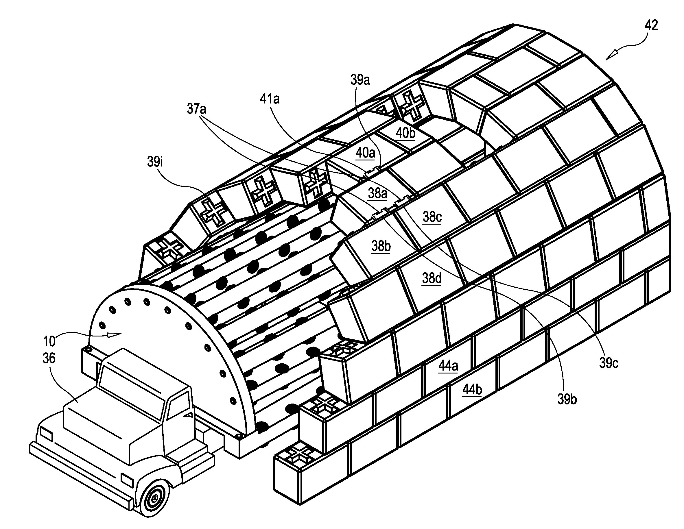
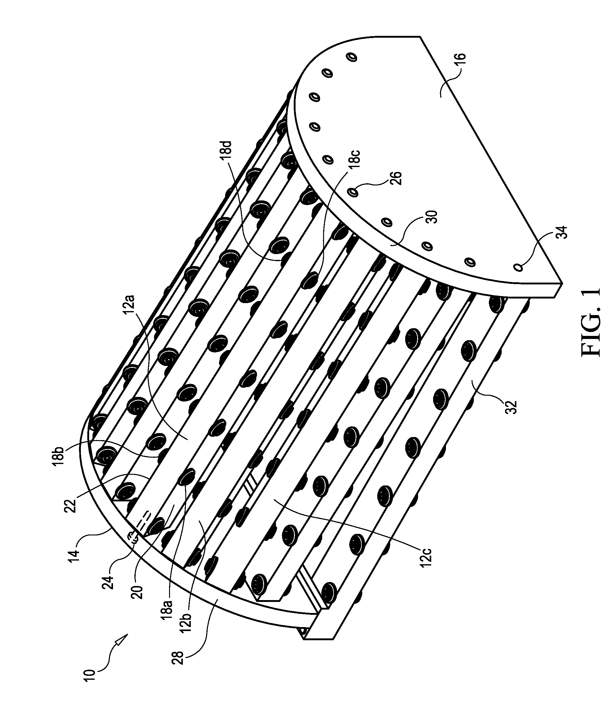
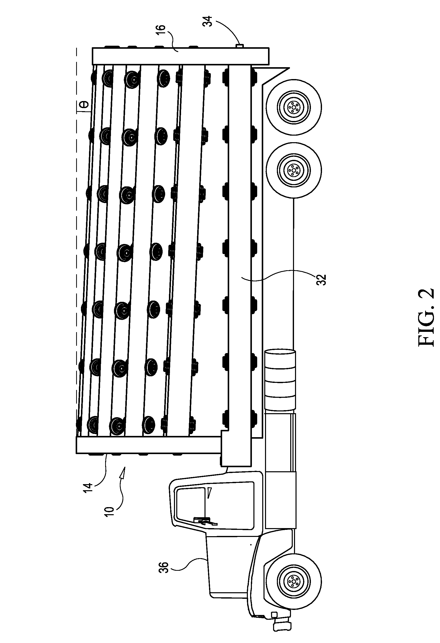
[0032]Referring to the drawings and first to FIG. 1, a first embodiment of an improved formwork 10 for use in the construction of an arched structure is shown. The formwork 10 includes a plurality of longitudinal members, for example longitudinal members 12a, 12b and 12c, which extend between end panels 14 and 16. The longitudinal members are substantially similar in structure and function. Accordingly, only one of the longitudinal members 12a is described in detail herein with the understanding that the remaining longitudinal members have a substantially similar structure and function in a substantially similar manner. The longitudinal member 12a has a plurality of spaced apart rollers, for example rollers 18a, 18b, 18c and 18d, disposed along a length thereof. In this example, the rollers are mounted as opposed pairs. Roller 18a is mounted on a first side 20 of the longitudinal member 12a opposite roller 18b which is mounted on a second side 22 of the longitudinal member 12a. Like...


PUM


Abstract

A formwork for constructing an arched structure comprises a first end panel and a second end panel. A plurality of longitudinal members extends between the first end panel and the second end panel. The longitudinal members are arranged in an arced formation and the longitudinal members slope between the first end panel and the second end panel. The formwork may have rollers disposed along lengths of the longitudinal members.

Description

CROSS-REFERENCE TO RELATED APPLICATIONS[0001]This application claims the benefit of provisional application 61 / 453,058 filed in the United States Patent and Trademark Office on Mar. 15, 2011 and provisional application 61 / 578,181 filed in the United States Patent and Trademark Office on Dec. 20, 2011, the disclosures of which are incorporated herein by reference and priority to which is claimed.BACKGROUND OF THE INVENTION[0002]1. Field of the Invention[0003]The present invention relates to the construction of arched structures and, in particular, to a formwork for use in the construction of arched structures and a method of constructing arched structures.[0004]2. Description of the Related Art[0005]It is known to use arched structures in bridges, culverts, sewers and tunnels among other things. Traditionally, arched structures were constructed by successively setting voussiors until a central voussior or keystone can be set. The arched structure then becomes complete and self-suppor...

Claims


Application Information

Patent Timeline
Patent Type & Authority Applications(United States)
IPC IPC(8): E04B1/32E04G21/16
CPCE21D11/08E21D11/40E04B1/3205E01D4/00E04B2001/327E04G11/36E04G21/1866E04B2001/3217E01F5/005E04B1/04E04B2001/3566
Inventor DREW, JAMES JOSEPH
Owner LOCK BLOCK LTD
Learn More