Fine particle sensor and mounting structure therefor

a technology of fine particle sensor and mounting structure, which is applied in the direction of instruments, electric supply techniques, machines/engines, etc., can solve the problem of the tendency of detection accuracy of conventional fine particle sensor, and achieve the effect of improving the detection accuracy of fine particles

Active Publication Date: 2012-09-20
NGK SPARK PLUG CO LTD
View PDF11 Cites 37 Cited by
  • Summary
  • Abstract
  • Description
  • Claims
  • Application Information

AI Technical Summary

Benefits of technology

[0004]It is therefore an object of the present invention to provide a technique for improving the accuracy...

Problems solved by technology

However, there is a problem that the detection accuracy of the conventional fine pa...

Method used


Image

  • Fine particle sensor and mounting structure therefor
  • Fine particle sensor and mounting structure therefor
  • Fine particle sensor and mounting structure therefor

Examples


first modification

[0101

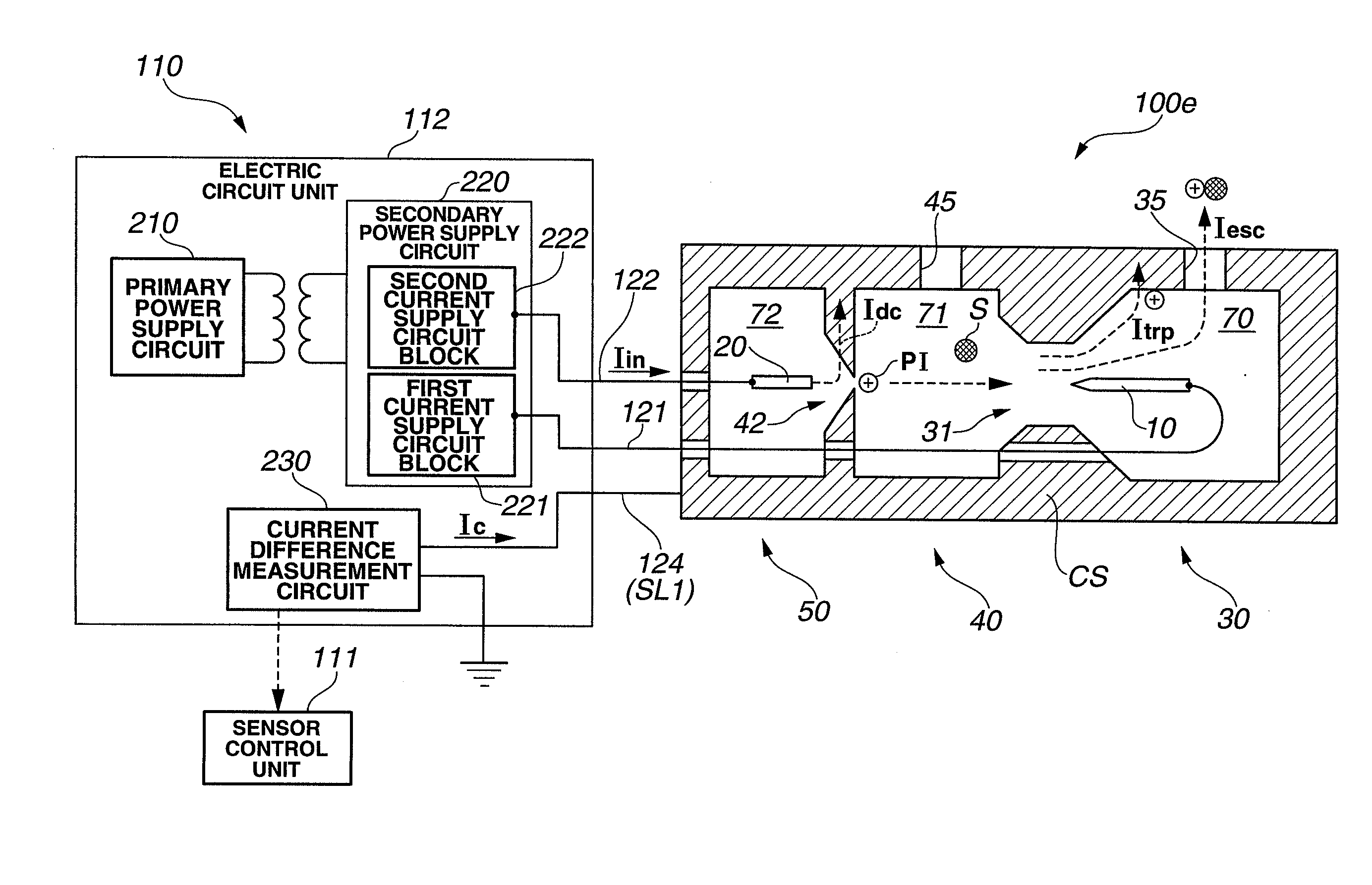
[0102]The ion generating unit, the charging unit and the ion trapping unit are arranged in the front end portion 100e of the fine particle sensor 100 in the above embodiment. The ion generating unit is not however necessarily arranged in the front end portion 100e of the fine particle sensor 100. At least the charging unit and the ion trapping unit can be arranged in the front end portion 100e of the fine particle sensor 100. That is, it is not necessary to accommodate the ion generating unit in the casing CS as long as at least the charging unit and the ion trapping unit are accommodated in the casing CS. In this case, the ion generating unit may be arranged in the fine particle sensor 100 at a position outside the exhaust pipe 415 and separate from the charging unit and the ion trapping unit.

second modification

[0103

[0104]The nozzle 42 is not necessarily formed in the partition wall 41 as a communication hole between the inner space 72 of the holder member 50 and the inner space 71 of the nozzle member 40 although the nozzle 42 is formed between these two inner spaces 72 and 71 in the above embodiment. However, there develops a negative pressure in the inner space 71 by the ejection of the air into the inner space 71 through the nozzle 42 so that the exhaust gas can be favorably introduced from the exhaust pipe 415 into the inner space 71 through the gas inlet hole 45 under suction as mentioned above. The formation of the nozzle 42 between the inner spaces 72 and 71 is thus effective to stabilize the amount of the exhaust gas introduced into the fine particle sensor 100 and improve the detection accuracy of the fine particle sensor 100.

third modification

[0105

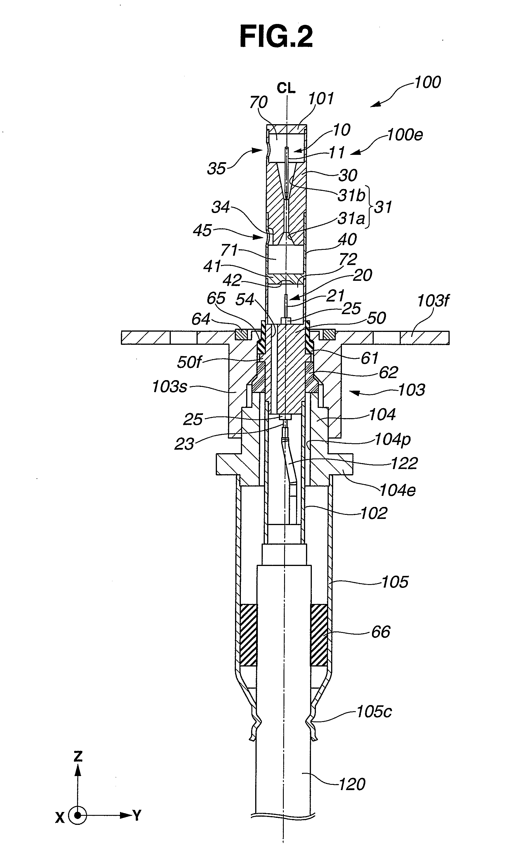
[0106]Although the front end portion 100e of the fine particle sensor 100 is inserted in the direction substantially perpendicular to the extension direction of the exhaust pipe 415 in the above embodiment, the direction of insertion of the front end portion 100e of the fine particle sensor 100 is not necessarily substantially perpendicular to the extension direction of the exhaust pipe 415 and may be inclined with respect to the extension direction of the exhaust pipe 415.


PUM


Abstract

There is provided a fine particle sensor for detecting fine particles in exhaust gas, including an ion generating unit for generating ions by corona discharge, a charging unit for charging the fine particles by some of the generated ions, an ion trapping ions for trapping a remainder of the generated ions and a casing for accommodating therein the charging unit and the ion trapping unit in a given arrangement direction. The casing has a gas inlet hole and a gas outlet hole formed in a circumferential wall thereof so that the exhaust gas flows in the charging unit through the gas inlet hole and flows out of the ion trapping unit through the gas outlet hole. The gas inlet hole and the gas outlet hole are arranged in such a manner as to at least partially overlap each other when viewed in the given arrangement direction.

Description

BACKGROUND OF THE INVENTION[0001]The present invention relates to a fine particle sensor for detecting fine particles (e.g. soot) in exhaust gas and a mounting structure for mounting a fine particle sensor to an exhaust pipe of an internal combustion engine.[0002]In the following description, the terms “front” and “rear” are used with respect to the axial direction of a fine particle sensor and, more specifically, the direction of insertion of the fine particle sensor into an exhaust pipe; and the terms “upstream” and “downstream” are used with reference to the direction of gas flow in the fine particle sensor or in the exhaust pipe.[0003]Fine particles (e.g. soot) are contained in exhaust gases of internal combustion engines (such as diesel engines and gasoline engines). It is thus common practice to mount a fine particle sensor on an exhaust pipe of the internal combustion engine in order to detect the amount of fine particles in the exhaust gas and limit the amount of fine partic...

Claims


Application Information

Patent Timeline
IPC IPC(8): B03C3/38
CPCF01N13/008G01N15/0656G01N1/2252F01N2560/05
Inventor SUGIYAMA, TAKESHIMOTOMURA, MASAYUKIMATSUOKA, TOSHIYATASHIMA, KEISUKEYOKOI, HITOSHI
Owner NGK SPARK PLUG CO LTD
Why Eureka
Try Eureka