
Structure of transmission line for data communication and method for designing the same

a transmission line and data communication technology, applied in the direction of waveguides, conductive pattern formation, high frequency circuit adaptations, etc., can solve the problems of increasing the size of the flexible pcb, the difficulty of using the signal line structure at the transmission speed of 10 gbps, etc., to achieve the effect of improving reflection and low cos

Inactive Publication Date: 2012-09-20
ELECTRONICS & TELECOMM RES INST
View PDF2 Cites 27 Cited by
  • Summary
  • Abstract
  • Description
  • Claims
  • Application Information

AI Technical Summary

Benefits of technology

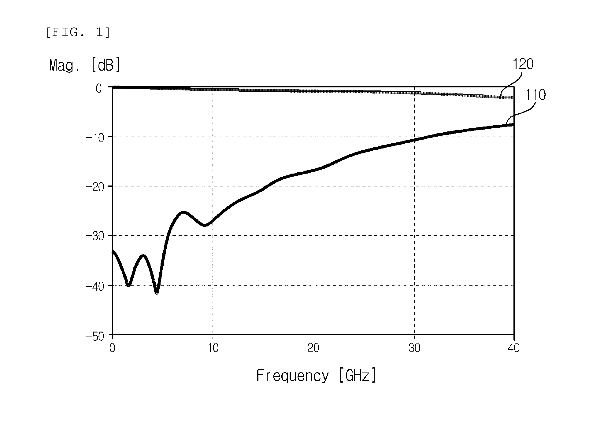
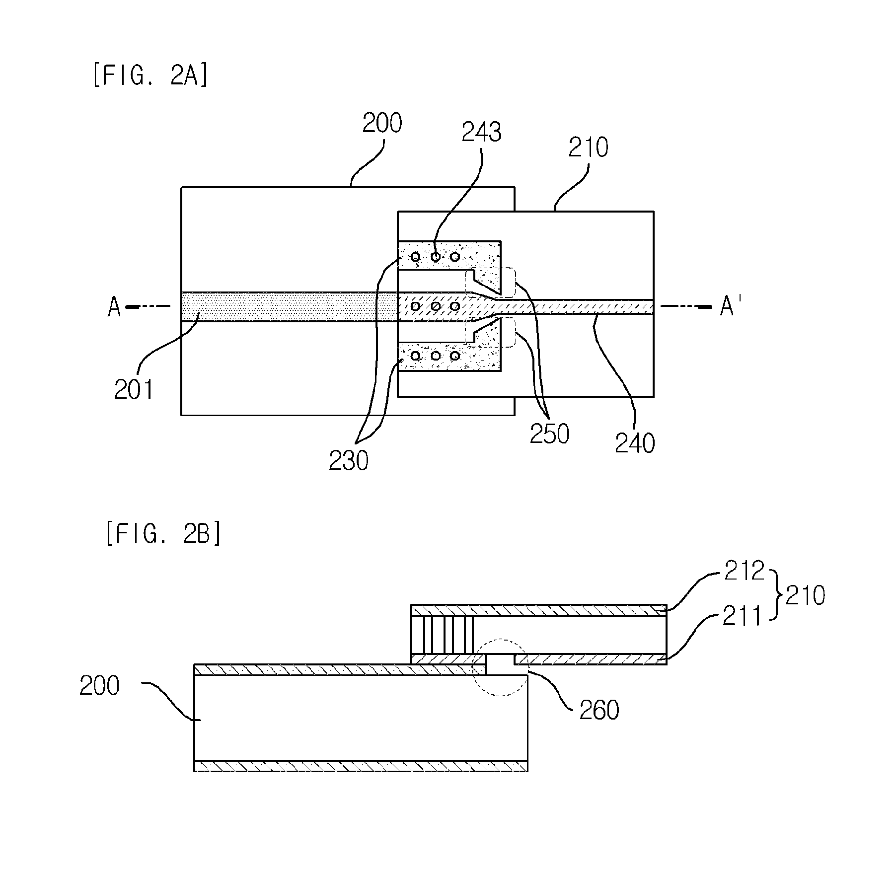
[0019]According to exemplary embodiments of the present invention, it is possible to largely improve a reflection by generating a resonance in a desired frequency band by impedance-matching data signal lines between the flexible PCB and the main board by using a coplanar waveguide (CPW) structure or an open stub of a micro-strip transmission line, thereby solving an impedance mismatch when a flexible PCB is electrically connected with a main board in a high-speed optical communication device. Further, a product can be produced by a fabricating process of the flexible PCB in the related art and a flexible PCB which can perform high-speed signal transmission may be fabricated at a low cost.

Problems solved by technology

Accordingly, it is difficult to use the signal line structure at the transmission speed of 10 Gbps level or more according to the increase in a reflection.
However, the method has disadvantages in that there is a limitation to a channel distance by a via hole when using a differential signal or various channel signals and the entire size of the flexible PCB increases because a distance between the via hole and the signal line needs to more increase at a higher frequency than the frequency band.

Method used


Image

  • Structure of transmission line for data communication and method for designing the same
  • Structure of transmission line for data communication and method for designing the same
  • Structure of transmission line for data communication and method for designing the same

Examples


Embodiment Construction

[0029]Hereinafter, exemplary embodiments of the present invention will be described in detail with reference to the accompanying drawings. First of all, we should note that in giving reference numerals to elements of each drawing, like reference numerals refer to like elements even though like elements are shown in different drawings. Further, in describing the present disclosure, well-known functions or constructions will not be described in detail since they may unnecessarily obscure the understanding of the present disclosure. Hereinafter, the exemplary embodiment of the present invention will be described, but it will be understood to those skilled in the art that the spirit and scope of the present invention are not limited thereto and various modifications and changes can be made.

[0030]The present invention provides a structure of a data signal line on a flexible PCB for electric connection of a high-speed optical communication device. Particularly, the present invention provi...


PUM

PropertyMeasurementUnit
impedanceaaaaaaaaaa
lengthaaaaaaaaaa
lengthaaaaaaaaaa

Abstract

Disclosed is a structure for impedance matching by applying a CPW structure to an impedance discontinuous portion on a data signal line or using a micro-strip open stub so as to be used for high-speed transmission by a flexible PCB. According to the present invention, it is possible to fabricate a flexible PCB capable of performing low-priced and high-speed transmission.

Description

CROSS-REFERENCE TO RELATED APPLICATIONS[0001]This application claims priority to and the benefit of Korean Patent Application No. 10-2011-0022970 filed in the Korean Intellectual Property Office on Mar. 15, 2011, the entire contents of which are incorporated herein by reference.TECHNICAL FIELD[0002]The present invention relates to a structure of a transmission line for data communication and a method for designing the same. More particularly, the present invention relates to a structure of a transmission line for data communication according to a printed circuit board (PCB) and a method for designing the same by using the printed circuit board (PCB).BACKGROUND ART[0003]A flexible PCB is one type of PCBs which are used for various uses in a communication system. The largest merit of the flexible PCB is in that the flexible PCB may provide a lot of degrees of freedom in the design of a system due to variability of shapes thereof. Currently, the flexible PCB is mainly used at a low tra...

Claims


Application Information

Patent Timeline
Patent Type & Authority Applications(United States)
IPC IPC(8): H01P3/08H05K3/10H03H7/38
CPCH01P3/006H01P5/028H05K1/0219H05K1/0227H05K1/0253Y10T29/49155H05K2201/058H05K2201/09618H05K2201/09672H05K2201/09727H05K2201/10121H05K1/147H01P1/203H03H7/38H05K1/14
Inventor KANG, SAE KYOUNGLEE, JOON KIHUH, JOON YOUNGLEE, JYUNG CHAN
Owner ELECTRONICS & TELECOMM RES INST
Learn More