Light-source control device, light-source control method, image reading device, and image forming apparatus

a control device and light source technology, applied in the direction of electrographic process, electrographic process apparatus, instruments, etc., can solve the problems of yellow fluorescent material having inferior emission response characteristics with respect to drive current, time-consuming to follow, and changing the color of light emitted by the white led

Inactive Publication Date: 2012-09-20
RICOH KK
View PDF16 Cites 52 Cited by
  • Summary
  • Abstract
  • Description
  • Claims
  • Application Information

AI Technical Summary

Benefits of technology

[0022]It is an object of the present invention to at least

Problems solved by technology

If the white LED is lighted up by using a PWM drive according to a conventional technology, there is a problem in that the color of light emitted by the white LED changes in accordance with any change in the duty ratio of the PWM signal during adjustment of the lighting intensity.
However, the yellow fluorescent material has inferior emission response characteristics with respect to the drive current as compared to the blue LED; therefore, it takes time to follow a change in the drive current (the period B in FIG. 22).
As described above, in the case of a white light source that

Method used


Image

  • Light-source control device, light-source control method, image reading device, and image forming apparatus
  • Light-source control device, light-source control method, image reading device, and image forming apparatus
  • Light-source control device, light-source control method, image reading device, and image forming apparatus

Examples


first embodiment

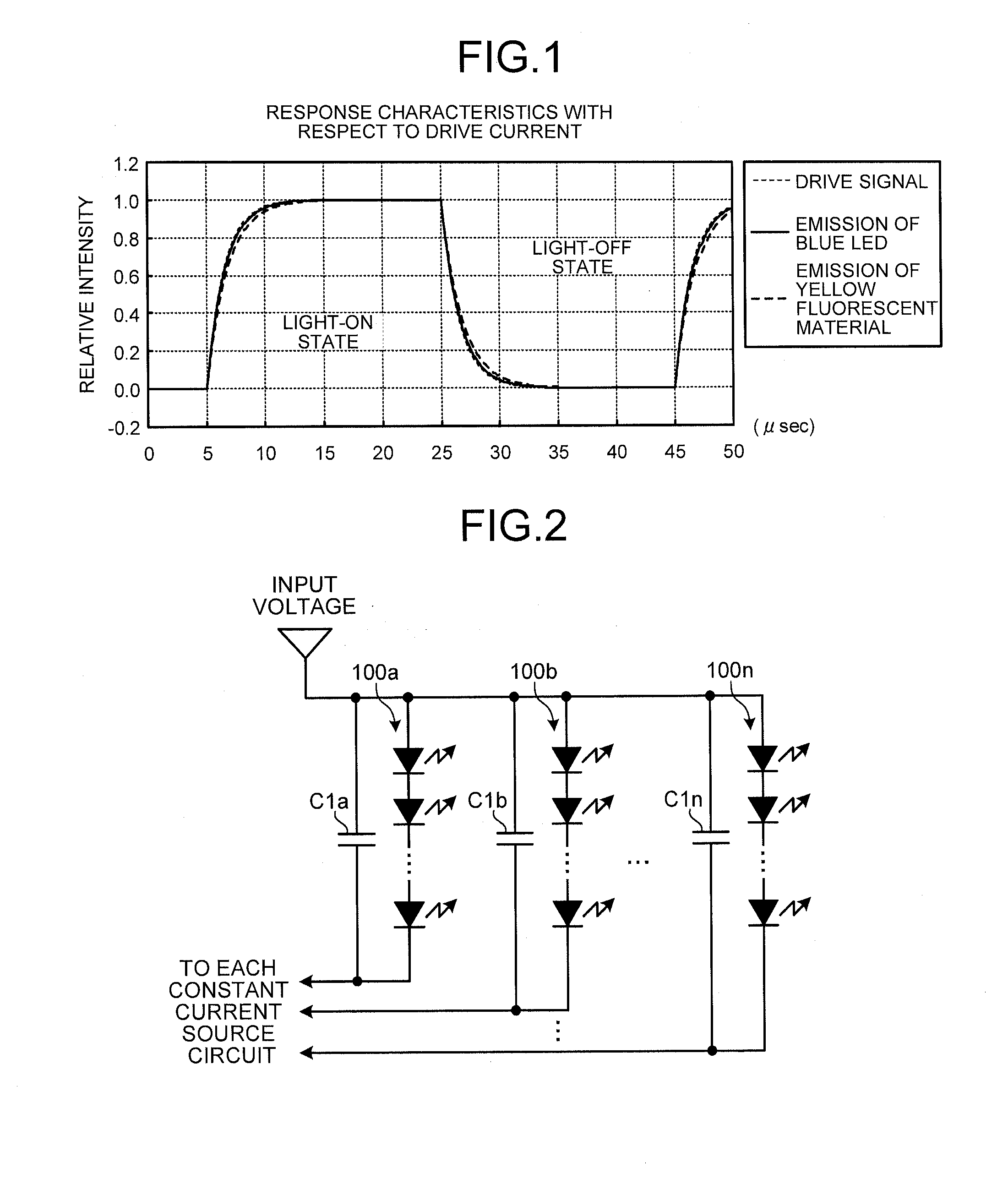
[0055]A first embodiment of a light-source control device according to the present invention is explained in detail below with reference to the accompanying drawings. Before the present invention is explained, various terms to be used in the following are defined. First, a light emitter that includes a blue LED and a yellow fluorescent material and that emits pseudo white light due to the light emission of the blue LED and the yellow fluorescent material is referred to as a white LED. A yellow phosphorescent material is used in place of the yellow fluorescent material.

[0056]The rise transition time is, if the difference between the current values obtained before and after the current is changed is 100%, the time it takes to change from a predetermined percentage (e.g., 10%) on the lower value side to a predetermined percentage (e.g., 90%) on the higher value side when the drive current rises. Similarly, the fall transition time is, if the difference between the current values obtain...

first modified example of first embodiment

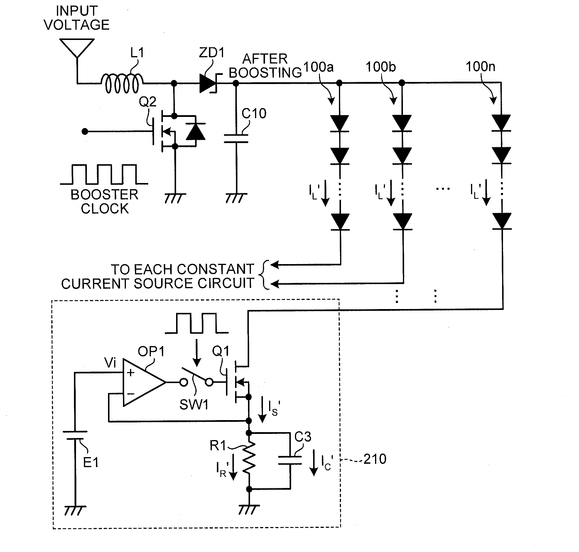
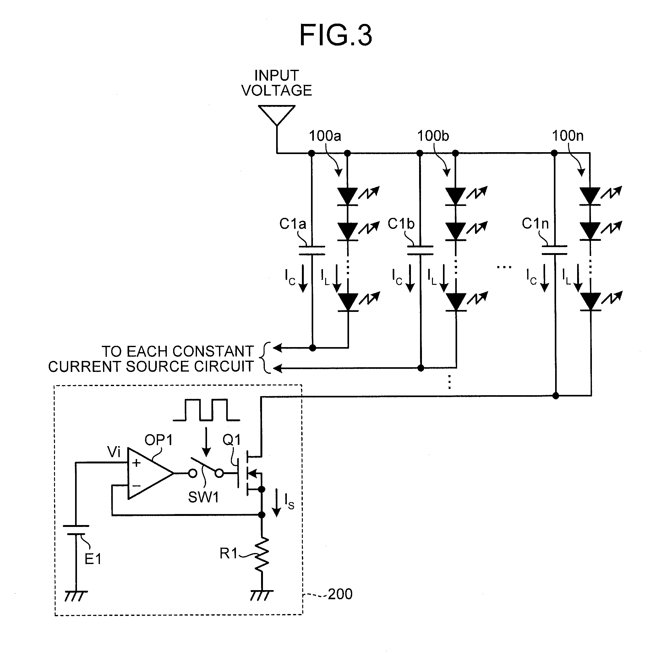
[0073]FIG. 5 illustrates an exemplary configuration of a drive circuit of a white LED according to a first modified example of the above-described first embodiment. In FIG. 5, the same components as those described in FIG. 2 are denoted by the same reference marks, and their detailed explanations are omitted. FIG. 5 does not illustrate the constant current circuit 200 that is connected to the cathode side of each of the white LED arrays 100a, 100b, . . . , 100n.

[0074]When the white LED is driven, an input voltage is boosted and applied to the white LED so that it is possible to increase the number of white LEDs connected in series, i.e., the total number of white LEDs driven. In the example illustrated in FIG. 5, a booster circuit is added to the configuration that is described above with reference to FIG. 2. The booster circuit includes a coil L1, a transistor Q2, a zener diode ZD1, and a capacitor C10. In the booster circuit, the accumulation and release of energy in and from the...

second modified example of first embodiment

[0078]FIG. 6 illustrates an exemplary configuration of a drive circuit of a white LED according to a second modified example of the above-described first embodiment. The second modified example is obtained by further modifying the first modified example of the first embodiment, which has been explained with reference to FIG. 5. In FIG. 6, the same components as those described in FIG. 5 are denoted by the same reference marks, and their detailed explanations are omitted. FIG. 6 does not illustrate the constant current circuit 200 that is connected to the cathode side of each of the white LED arrays 100a, 100b, . . . , 100n.

[0079]In the second modified example, when an input voltage is boosted and the boosted voltage is applied to each of the white LED arrays 100a, 100b, . . . , 100n, an unboosted input voltage or any power is applied to capacitors C3a, C3b, . . . , C3n that each have one end connected to the cathode side of the white LED arrays 100a, 100b, . . . , 100n.

[0080]As de...


PUM


Abstract

A light-source control device includes a light source including a first light emitter for emitting light and a second light emitter for emitting light due to the light emitted by the first light emitter; a constant current unit configured to maintain a current constant that is input via the light source from a power supply; a switching unit configured to switch the current to be input to the constant current unit at a designated duty ratio and cycle; and a control unit configured to control the current applied to the light source so that a rise transition time and a fall transition time of the current applied to the light source are nearly equal to each other.

Description

CROSS-REFERENCE TO RELATED APPLICATIONS[0001]The present application claims priority to and incorporates by reference the entire contents of Japanese Patent Application No. 2011-061681 filed in Japan on Mar. 18, 2011.BACKGROUND OF THE INVENTION[0002]1. Field of the Invention[0003]The present invention relates to a light-source control device, a light-source control method, an image reading device, and an image forming apparatus.[0004]2. Description of the Related Art[0005]A conventional method is known which uses a chip light emitting diode (LED) as a light source that is included in a scanner device and emits white light. LEDs have a superior responsiveness than conventional xenon lamps; therefore, the lighting intensity of an LED can be controlled by using a pulse width modulation (PWM) drive to control the lighting-up time. A method of controlling LEDs using PWM drives has already been put to practical use.[0006]For example, Japanese Patent No. 3368890 discloses a technology in w...

Claims


Application Information

Patent Timeline
IPC IPC(8): H04N1/04G03G15/043H05B37/02
CPCH04N1/40056G03G15/04054H05B33/0827H05B33/0818G03G15/043H05B45/38H05B45/46
Inventor OYAMA, TADAAKI
Owner RICOH KK
Why Eureka
Try Eureka