Optical transceiver with inner fiber set within tray securing thermal path from electronic device to housing

a technology of optical transceivers and inner fibers, applied in the field of optical communication accessories, can solve the problems of reducing the process tolerance of the assembly of inner fibers with optical connectors, reducing the production cost of optical transceivers, and disadvantages of integrated types and discrete types, so as to achieve efficient heat dissipation and conduct heat

Inactive Publication Date: 2012-09-20
SUMITOMO ELECTRIC IND LTD
View PDF4 Cites 28 Cited by
  • Summary
  • Abstract
  • Description
  • Claims
  • Application Information

AI Technical Summary

Benefits of technology

[0009]Because the tray in the optical transceiver may provide functions not only to guide the inner fiber but to secure the heat dissipating path, the wiring of the inner fiber within the housing may be substantially independent of the position of the electronic component. That is, the position of the electronic component does not interfere with the wiring of the inner fiber. The tray may be in contact with both of the electronic component and the housing, or the tray may be in indirectly contact with the electronic component via a thermal sheet, or may fill a space, in which the inner fiber is guided, with a thermal gel. Both the thermal sheet and the thermal gel may enhance the heat dissipating function, or reduce the thermal resistance between the electronic component and the housing.
[0011]Because inner fibers are likely to be disordered within the housing, some members such as fiber tray to set the disordered inner fibers therein are inevitable. However, such members often interfere with physical functions of other components, for instance, a mechanism to dissipate heat from electronic circuits to an outside of the housing. The tray according to an embodiment of the present application may show a function to guide inner fiber and to conduct heat efficiently from the electronic circuit.

Problems solved by technology

On the other hand, the integrated type inherently has disadvantages in points that, when at least one of optical transmitter or the optical receiver falls into trouble, the whole components of the optical transmitter / receiver and the optical multiplexer / de-multiplexer are necessary to be replaced, which drastically increases the production cost of the optical transceiver.
The inner fibers need to be distributed to escape from the thermal block, which inevitably results in the condition to reduce the process tolerance of the assembly of the inner fibers with the optical connector.
Thus, both the integrated type and the discrete type have disadvantages peculiar to the respective types.
However, such members often interfere with physical functions of other components, for instance, a mechanism to dissipate heat from electronic circuits to an outside of the housing.

Method used


Image

  • Optical transceiver with inner fiber set within tray securing thermal path from electronic device to housing
  • Optical transceiver with inner fiber set within tray securing thermal path from electronic device to housing
  • Optical transceiver with inner fiber set within tray securing thermal path from electronic device to housing

Examples


Embodiment Construction

[0026]Next, some preferred embodiments of an optical transceiver according to the preset invention will be described as referring to accompanying drawings. In the description of the drawings, the numerals or symbols same or similar to each other will refer to the elements same or similar to each other without overlapping explanations.

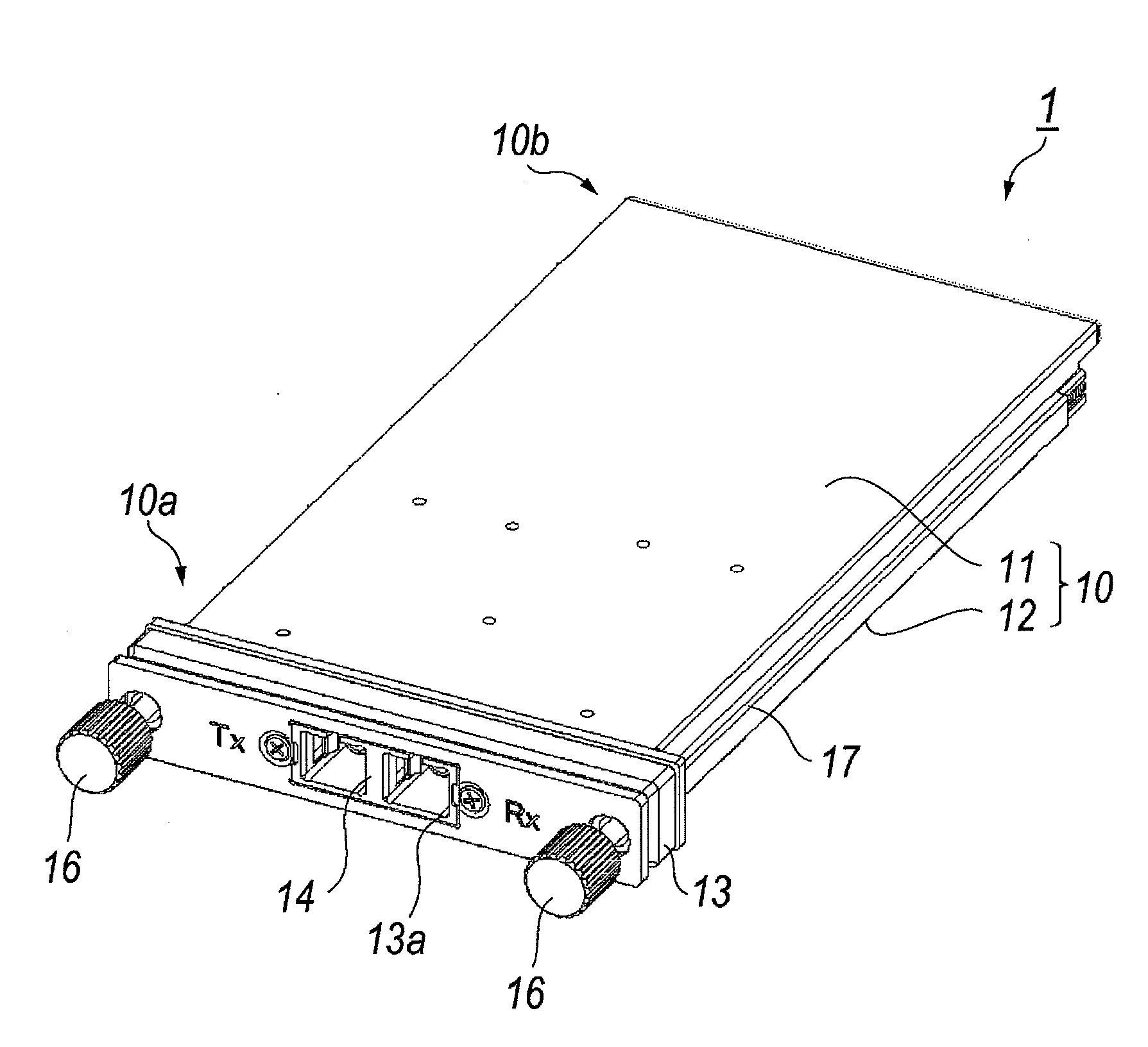
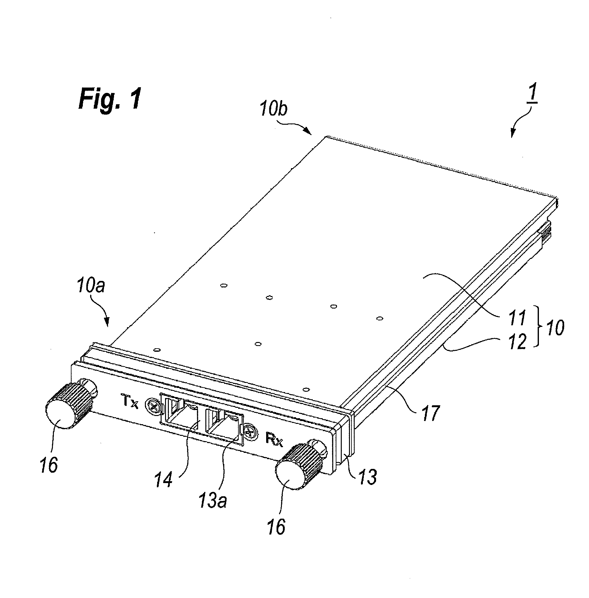
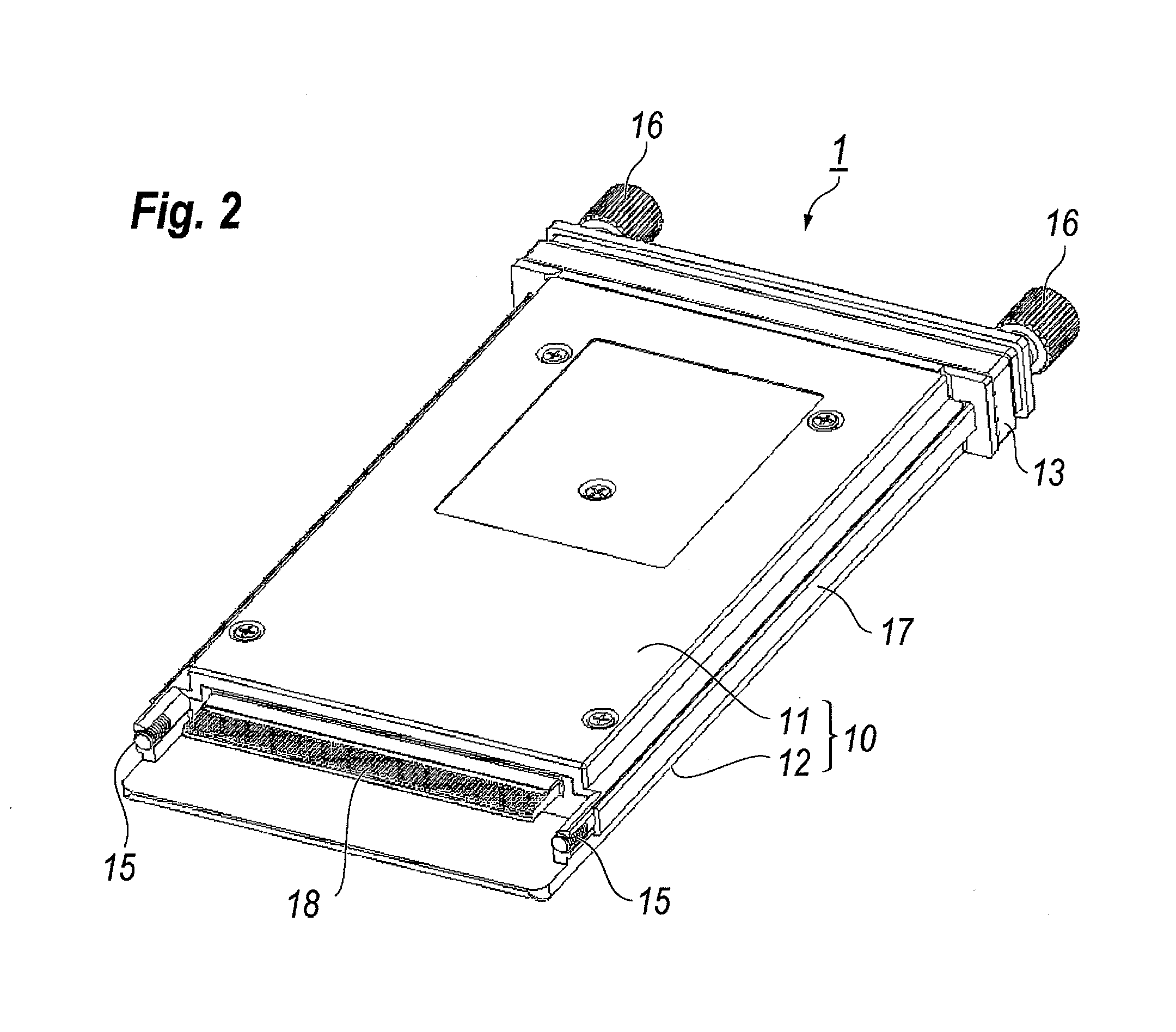
[0027]FIG. 1 is a perspective illustration viewed from a front top of an optical transceiver according to an embodiment of the present invention; while, FIG. 2 is also a perspective illustration of the optical transceiver viewed from the rear bottom thereof. The optical transceiver 1 shown in FIGS. 1 and 2 is a type of, what is called, the pluggable optical transceiver following the standard of the CFP. The optical transceiver 1 provides a housing 10 constituted by a bottom housing 11 and a top housing 12 to secure an inner space in which electronic and / or optical components are installed. The bottom and top housings may be made of metal such as aluminu...


PUM


Abstract

An optical transceiver with inner fibers to couple optical parts installed therein is disclosed. The optical transceiver of an embodiment includes a tray for arranging the inner fibers. The tray, which may be made of metal plate, includes a primary plane in contact with the electronic parts, the contact plane in contact with the housing, and the turn connecting the planes. The tray has a U-shaped cross section with a space surrounded by both planes, the turn, and the housing, where the inner fibers are secured in the space.

Description

RELATED APPLICATIONS[0001]This application is a continuation-in-part application of and claims a benefit of priority from U.S. Patent application Ser. No. 12 / 916,080, filed on Oct. 29, 2010, which is based on and claims a benefit of U.S. Provisional patent applications Ser. No. 61 / 261,105 filed on Nov. 13, 2009, and Ser. No. 61 / 314,801 filed on Mar. 17, 2010. The entire contents of these applications are incorporated herein by reference.BACKGROUND OF THE INVENTION[0002]1. Field[0003]An embodiment of the present invention relates to an apparatus for the optical communication.BACKGROUND[0004]A multi-source agreement (MSA) accessible as “CFP MSA Hardware Specification Revision 1.4” in the internet, <http: / / www.cfp-msa.org>, has designed an optical transceiver implemented with an optical multiplexer / de-multiplexer and optical transmitter / receiver. The optical transceiver designed therein realizes the optical communication with the transmission capacity of 40 Gbit / s by multiplexing...

Claims


Application Information

Patent Timeline
Patent Type & Authority Applications(United States)
IPC IPC(8): G02B6/36G02B6/42
CPCG02B6/3821G02B6/3825G02B6/3878G02B6/4292G02B6/4201G02B6/421G02B6/4246G02B6/3897G02B6/4243G02B6/4256G02B6/4261G02B6/4274G02B6/4277G02B6/428G02B6/4284
Inventor OKI, KAZUSHIGE
Owner SUMITOMO ELECTRIC IND LTD
Why Eureka
Try Eureka