Optically switched communication network

a communication network and optically switched technology, applied in multiplex communication, electrical equipment, wavelength-division multiplex systems, etc., can solve problems such as security threats to conventional mpc networks, and achieve the effects of reducing network energy needs, high operating expenses, and high scale performan

Inactive Publication Date: 2012-09-20
TREX ENTERPRISES CORP
View PDF6 Cites 7 Cited by
  • Summary
  • Abstract
  • Description
  • Claims
  • Application Information

AI Technical Summary

Benefits of technology

[0019]Packet processing at each network element makes conventional MPC networks vulnerable to security threats. By obviating packet processing, the network of the present invention is inherently more secure. This benefit is of particular importance when geographically dispersed massive parallel computing (MPC) platforms are functionally consolidated to achieve higher scale performance.
[0020]Today's densely interconnected MPC platforms cannot scale beyond a few tens of thousands of servers, far short of what would be demanded by critical applications suc

Problems solved by technology

Packet processing at each network element makes conv

Method used


Image

  • Optically switched communication network
  • Optically switched communication network
  • Optically switched communication network

Examples


first preferred embodiment

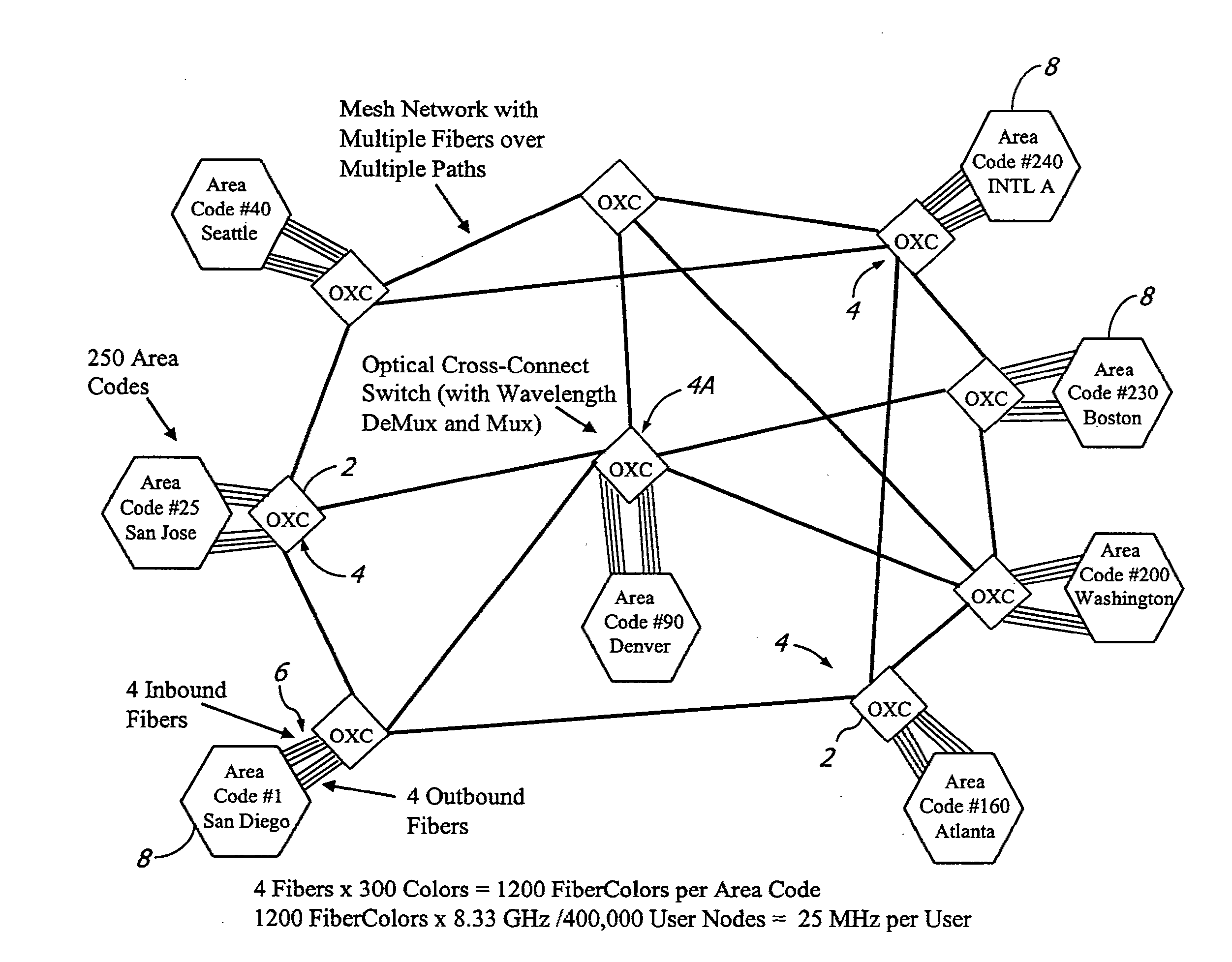
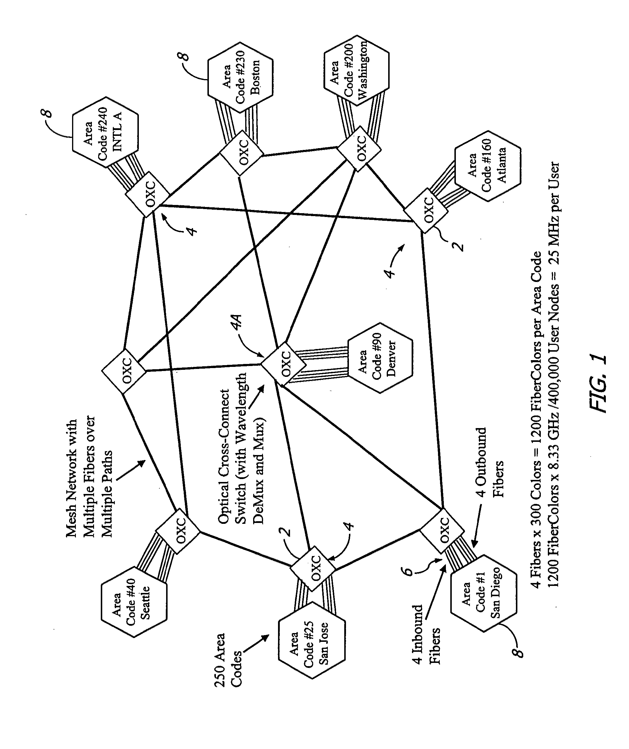
[0034]A top level description of a first preferred embodiment is shown in FIG. 1. In the discussion which follows, it should be understood that all quantities refer to a specific example of how the network might be implemented in a self-consistent manner, but that any specific numbers could be modified as the result of a more detailed analysis for a specific real world implementation. Here, for the first preferred embodiment, we consider a nation-scale network with end users assigned to one of 250 area codes with roughly equal numbers of end users in each. For instance, area code #1 has been assigned to San Diego, #40 to Seattle, #200 to Washington D.C., and #240 to some subset of international users. The proposed network can have about 400,000 User Nodes per Area Code. As seen in FIG. 1, Optical Cross-Connect switches (OXC's) 2 associated with each area code are located at mesh nodes 4 tied together in a mesh network which allows switching of optical signals from any particular are...

example

[0110]By reference to FIG. 16, the following is an example communication using the network described above.

[0111]The caller in San Diego is connected electrically to a local modem 57, sends a request to the modem for a link to Washington as shown at 59. The modem forwards this request to the San Diego area code computer to receive a sub-channel on one of the FiberColors assigned to Washington. Here, 2 FiberColors have already been given to the San Diego to Washington connection due to the recent traffic requirements. The San Diego computer picks an available frequency range for the sub-channel, and informs the modem at 58, the Washington computer, and the appropriate modem in Washington. The modems then have a direct link and data can be transferred. The Washington modem electrically sends the data to the called party nearby.

[0112]Before this happened, due to demands, San Diego had requested from the core allocation computer 2 FiberColors for the link to Washington as shown at 62. T...


PUM


Abstract

A large communication network suitable for nationwide or worldwide utilization. The present invention overthrows the conventional packet switching technologies with an all-optical network. The invention uses tunable laser sources to generate large number of highly stable narrow-band optical signals, each serving as a communication channel. With packet processing replaced by all-optical channels, the network become highly secure and scalable while harnessing the virtually unlimited capacity of fiber-optic. A large number of nodes (called area code nodes) are connected with all-fiber-optic links with all-optical switches. A routing algorithm provides one or more communication links from each area code node to every other area code node so that information never has to change carrier wavelength as it travels the network. Each area code node contains circuits that are provided to connect individual users to the network.

Description

[0001]This application is a continuation in part of U.S. patent application Ser. No. 10 / 677,590 filed Oct. 2, 2003. The present invention relates to communication networks and in particular to large optically switched communication networks.BACKGROUND OF THE INVENTIONHigh Data Rate Communication[0002]High date rate optical communication systems are well known. The communication industries have developed standards to facilitate interconnectivity among various communication suppliers. One popular standard utilizing time division multiplexing (TDM) to transmit information at high data rates through optical fibers is OC-48 / STM-16 which provides data rates at 2.5 Gbps. Other standards at higher data rates are available but OC-192 / STM-64 at 10 Gbps represents a current practical upper limit for TDM, with some success at 40 Gbps. Higher data rate can be provided with wavelength multiplexing in which data is multiplexed according to wavelength and time. Modern systems can routinely pack 40 ...

Claims


Application Information

Patent Timeline
IPC IPC(8): H04J14/02H04Q11/00
CPCH04J14/0212H04Q2011/0073H04J14/0234H04J14/0246H04J14/0247H04J14/025H04J14/0252H04J14/0257H04J14/028H04J14/0282H04J14/0284H04J14/0286H04J14/0298H04Q11/0062H04Q11/0071H04J14/0217
Inventor SPIVEY, BRETTKOREVAAR, ERICTIGLI, HUSBARRETT, TODD
Owner TREX ENTERPRISES CORP
Why Eureka
Try Eureka