Vehicle driving support apparatus

a technology for supporting apparatus and vehicles, which is applied in the direction of braking systems, instruments, analogue processes for specific applications, etc., can solve the problems of increasing braking pressure, achieve good ride comfort, reduce discomfort, and suppress pitching vibration

Active Publication Date: 2012-09-20
SUBARU CORP
View PDF2 Cites 35 Cited by
  • Summary
  • Abstract
  • Description
  • Claims
  • Application Information

AI Technical Summary

Benefits of technology

[0010]The present invention is accomplished in view of the above-mentioned circumstance, and aims to provide a vehicle driving support apparatus that suppresses a pitching vibration, which is generated before and after a vehicle stops when the automatic braking is operated, without additionally mounting a special sensor, thereby reducing an uncomfortable feeling given to a passenger, and providing good ride comfort.
[0011]An aspect of the present invention provides a vehicle driving support apparatus including: a forward-monitoring unit that is mounted on a vehicle for monitoring a driving environment ahead of the vehicle in advancing direction thereof; a time-to-collision calculating unit that detects an obstacle ahead based upon the driving environment ahead of the vehicle, which is detected by the forward-monitoring unit, and obtains a time-to-collision based upon an obstacle-to-vehicle distance between the obstacle ahead and the vehicle and a relative vehicle speed; and an automatic braking control unit that operates an automatic braking, reduces a braking pressure immediately before a target stopping position, and increases the braking pressure until immediately before the vehicle stops, when the time-to-collision obtained by the time-to-collision calculating unit is less than a predetermined braking assist determination time. The automatic braking control unit obtains a braking pressure reduction start distance between the obstacle ahead and the vehicle based upon a deceleration during the operation of the automatic braking. When the obstacle-to-vehicle distance reaches the pressure reduction start distance, the automatic braking control unit reduces the braking pressure. Then, when the obstacle-to-vehicle distance reaches a predetermined stopping braking start distance immediately before the vehicle stops, it increases the braking pressure.

Problems solved by technology

Then, when the obstacle-to-vehicle distance reaches a predetermined stopping braking start distance immediately before the vehicle stops, it increases the braking pressure.

Method used


Image

  • Vehicle driving support apparatus
  • Vehicle driving support apparatus
  • Vehicle driving support apparatus

Examples


Embodiment Construction

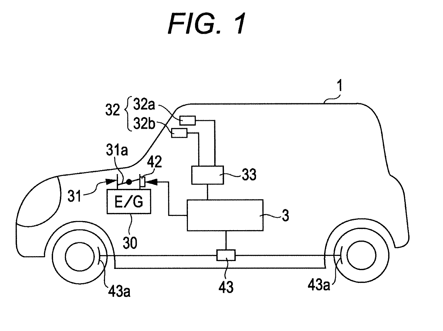
[0017]An embodiment of the present invention will be described with reference to the drawings. A vehicle 1 in FIG. 1 has mounted thereon an onboard camera 32 serving as a forward-monitoring unit. The onboard camera 32 is a stereo camera including a main camera 32a and a sub-camera 32b. An image of a driving environment ahead in the driving direction captured by the cameras 32a and 32b is subjected to a predetermined image process and output by an image processing unit (IPU) 33.

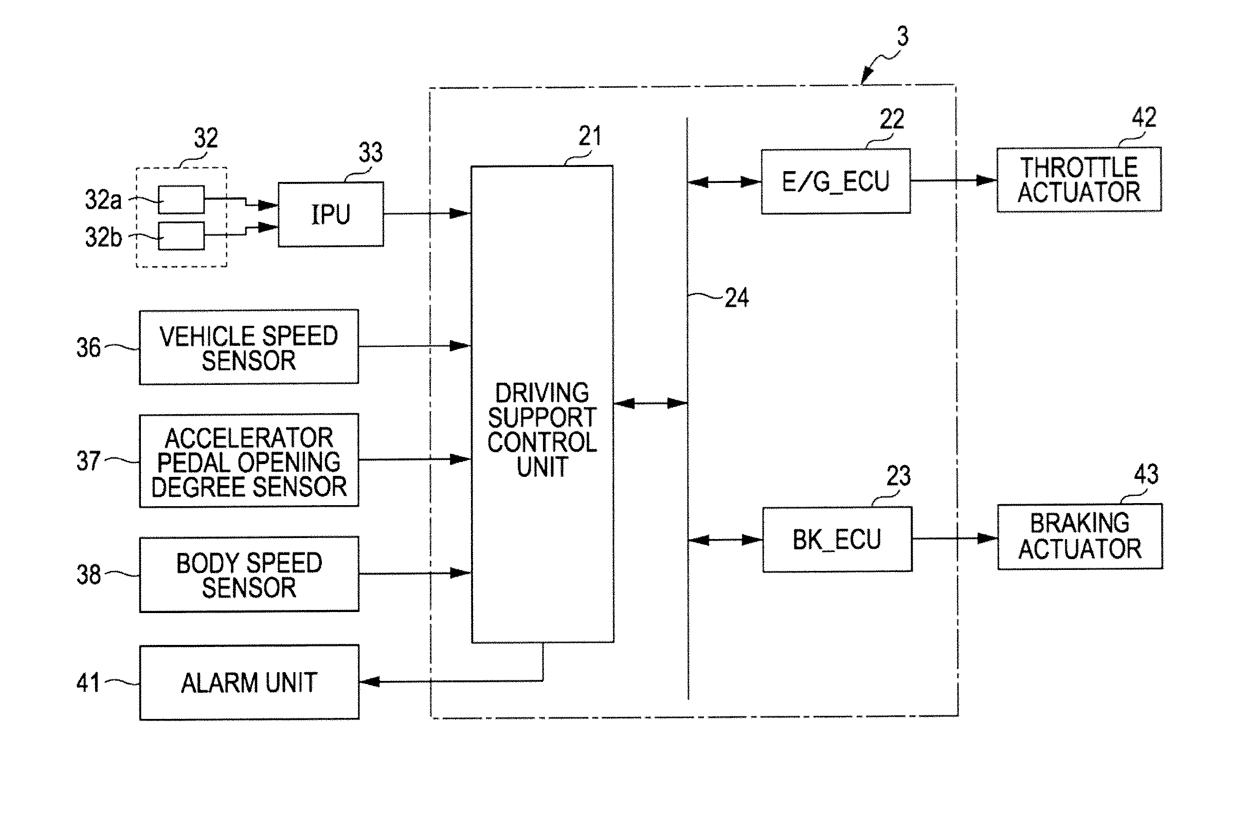
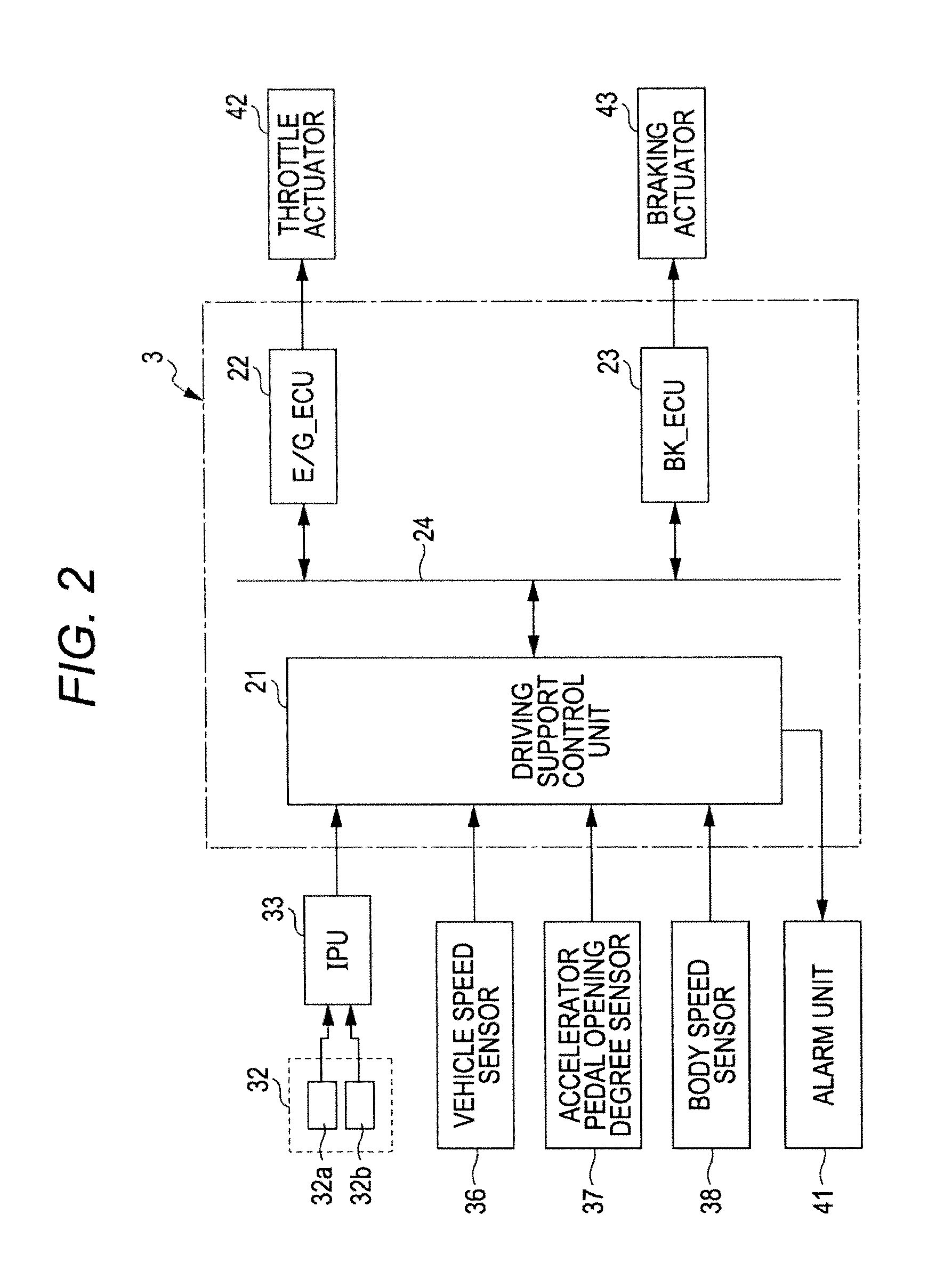
[0018]As illustrated in FIG. 2, a vehicle driving support apparatus 3 includes various control units such as a driving support control unit 21, an engine control unit (hereinafter referred to as a “E / G ECU”) 22, and a braking control unit (hereinafter referred to as “BK ECU”) 23. The control units are interconnected via an in-vehicle communication line 24 such as CAN (Controller Area Network). Each of the units 21 to 23 are composed of a microcomputer including a CPU, ROM, RAM, and the like, and the ROM stores...


PUM


Abstract

A pressure reduction start distance is obtained (S9) based upon a deceleration after an operation of an automatic brake. When an obstacle-to-vehicle distance between a vehicle and an obstacle ahead becomes a distance obtained by adding the pressure reduction start distance to a target stopping distance to the obstacle ahead, the reduction of the brake pressure is started (S11) to suppress a pitching vibration generated before and after the vehicle stops. When the obstacle-to-vehicle distance becomes a stopping brake start distance that is just before the target stopping distance, the brake pressure is increased (S13) so as to allow the vehicle to stop.

Description

CROSS-REFERENCE TO RELATED APPLICATIONS[0001]The present application claims priority from Japanese Patent Application No. 2011-058395 filed on Mar. 16, 2011, the entire contents of which are hereby incorporated by reference.BACKGROUND OF THE INVENTION[0002]1. Field of the Invention[0003]The present invention relates to a vehicle driving support apparatus that prevents an occurrence of a pitching vibration before and after a vehicle stops due to an operation of an automatic braking.[0004]2. Description of Related Art[0005]A driving support apparatus represented by an ACC (Adaptive Cruise Control) system or a pre-crash control system conventionally often employs an onboard camera or a radar device as a unit for monitoring an environment in front of a subject vehicle. The ACC system controls a vehicle speed, following a preceding vehicle that is travelling in front of the subject vehicle. When it is determined that the subject vehicle approaches rapidly to the preceding vehicle, and a ...

Claims


Application Information

Patent Timeline
Patent Type & Authority Applications(United States)
IPC IPC(8): B60T7/12
CPCB60T7/22B60T2201/02B60W30/0953B60W10/188B60W30/09B60T2230/04
Inventor KATO, HIROKIKII, YUJI
Owner SUBARU CORP
Why Eureka
Try Eureka