Lubricant supply system and method for controlling gearbox lubrication

a technology of lubricant supply system and gearbox, which is applied in the direction of mechanical equipment, gearing details, machines/engines, etc., can solve the problems of high pressure and unsafe pump operation

Inactive Publication Date: 2012-09-27
GENERAL ELECTRIC CO
View PDF23 Cites 32 Cited by
  • Summary
  • Abstract
  • Description
  • Claims
  • Application Information

AI Technical Summary

Benefits of technology

[0007]According to one aspect of the invention, a lubricant supply system (e.g., for a wind turbine) includes a lubricant flow circuit having, in fluid flow sequence: a variable-flow rate first pump; a lubricant cooler; and a gearbox. The apparatus also includes: a first temperature sensor for sensing a temperature of lubricant circulating within the lubr

Problems solved by technology

However, at very low temperatures, high oil viscosity may result in very hi

Method used


Image

  • Lubricant supply system and method for controlling gearbox lubrication
  • Lubricant supply system and method for controlling gearbox lubrication
  • Lubricant supply system and method for controlling gearbox lubrication

Examples


Embodiment Construction

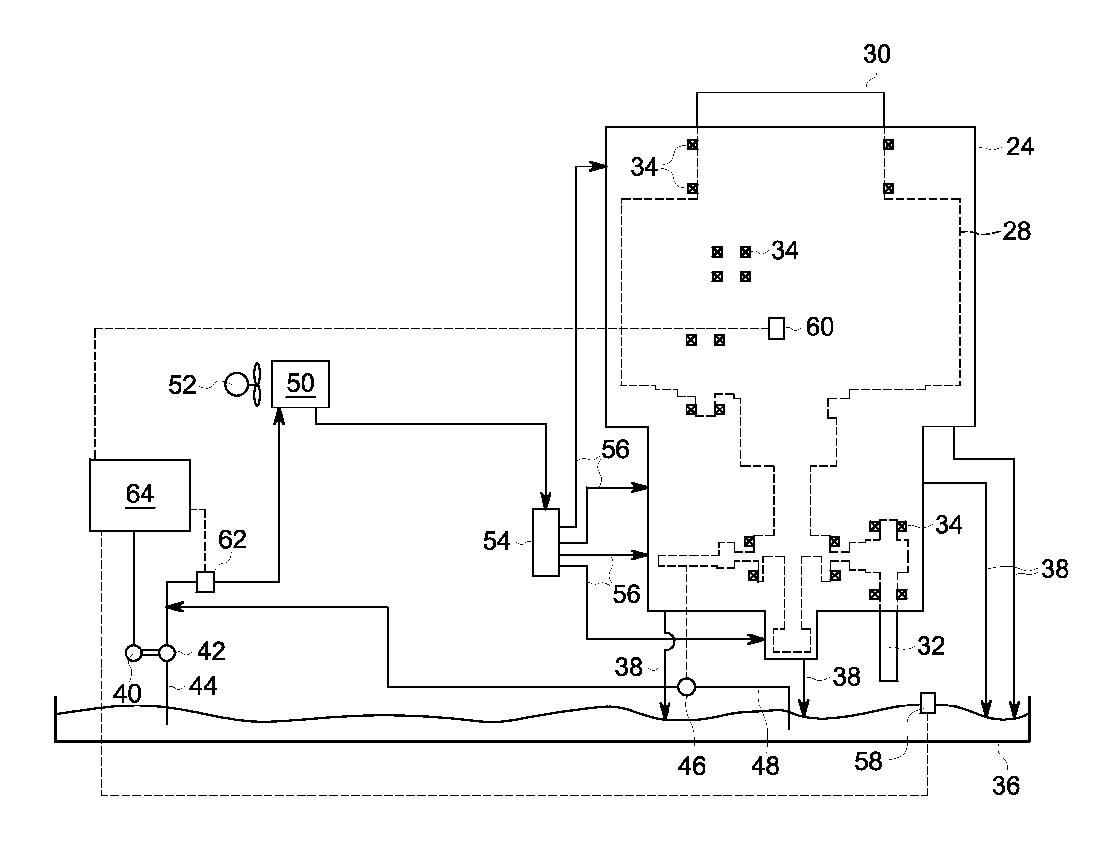
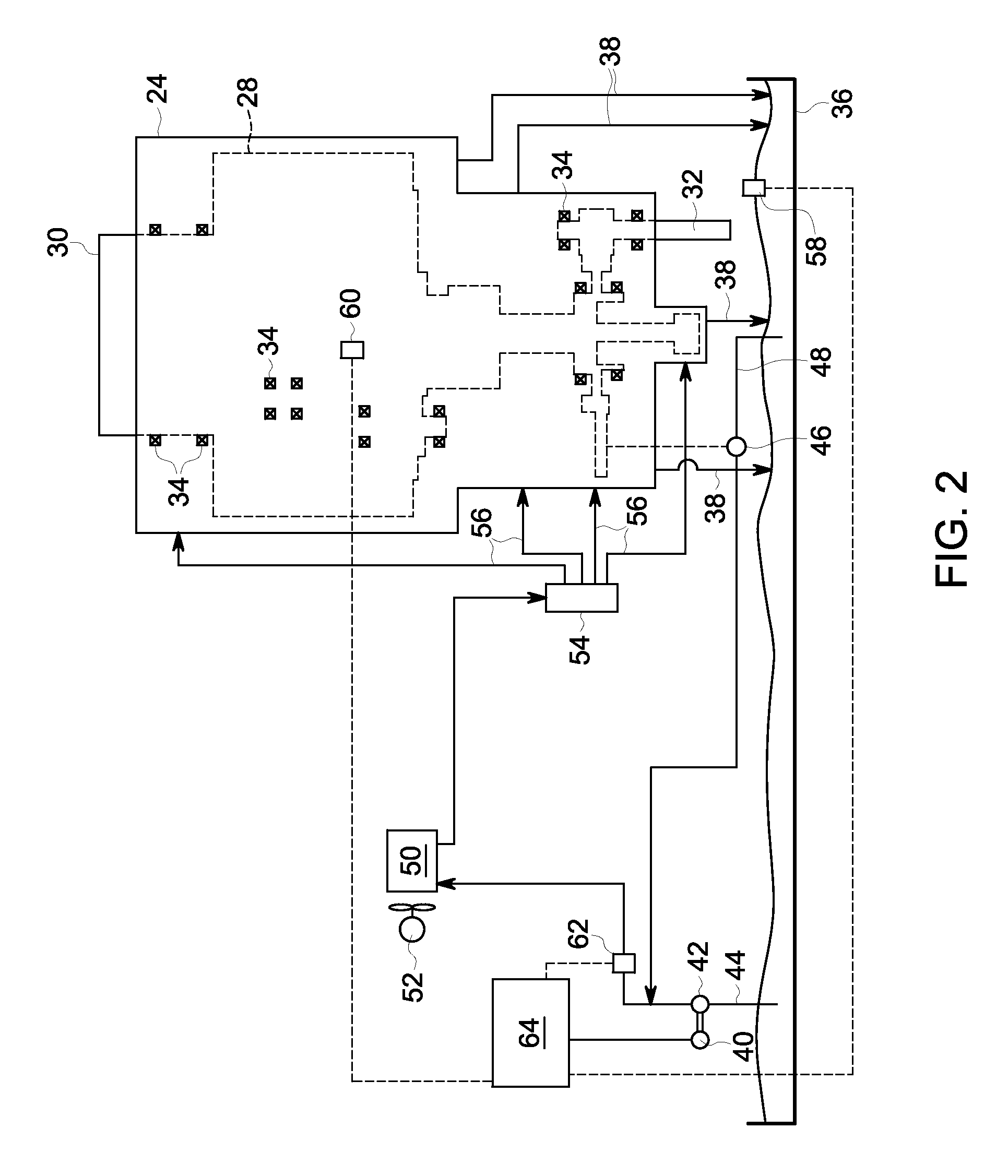
[0012]Referring to the drawings wherein identical reference numerals denote the same elements throughout the various views, embodiments of the invention relate to a lubricant supply system (generally shown in FIG. 2), e.g., for a wind turbine. Other embodiments relate to methods for controlling gearbox lubrication, e.g., for a wind turbine.

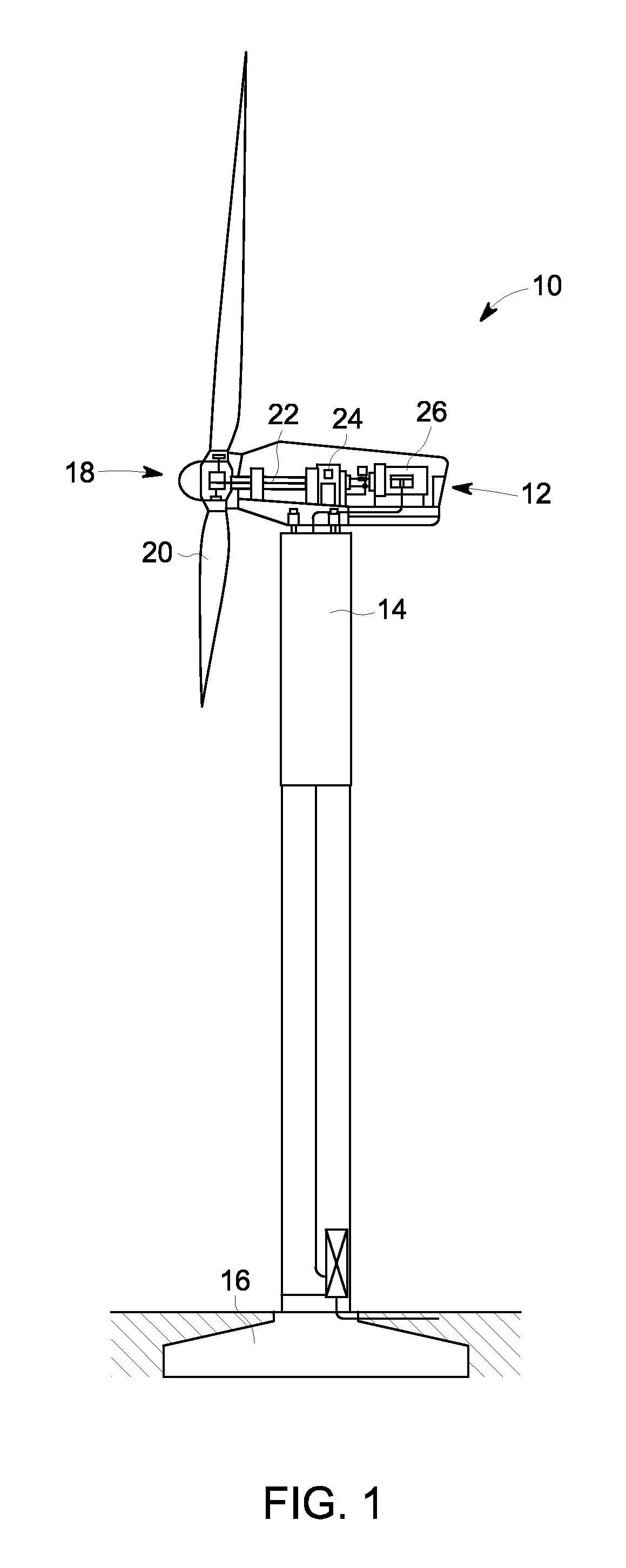
[0013]FIG. 1 depicts a wind turbine 10 including a nacelle 12 mounted on the upper end of a tower 14. The tower 14 is anchored to the ground via foundations 16. A rotor 18 having blades 20 is mounted on one end of the nacelle 12. A rotor shaft 22 couples the rotor 18 to a gearbox 24, which is in turn coupled to a generator (or alternator) 26.

[0014]The gearbox 24, shown in FIG. 2, houses a multi-stage planetary gearset 28 of a known type (shown schematically). The gearset 28 is coupled to the rotor shaft 22 by an input shaft 30 located at an “upwind” end, and is coupled to the generator 26 by a pinion shaft 32 at a “downwind” end. In operation, the...


PUM


Abstract

A lubricant supply system for a gearbox includes a lubricant flow circuit having, in fluid flow sequence: a variable-flow rate first pump; an lubricant cooler; and a gearbox. The system also includes: a first temperature sensor for sensing a temperature of lubricant circulating within the lubricant flow circuit; a pressure sensor for sensing a pressure of lubricant circulating within the lubricant flow circuit; and a controller operably connected to the pressure and temperature sensors and to the first pump. The controller is operable to control flow of the pump in response to the sensed temperature and to the sensed pressure.

Description

BACKGROUND OF THE INVENTION[0001]Embodiments of the invention relate generally to gearboxes. Other embodiments relate to lubrication of gearboxes subject to changing operational conditions.[0002]A wind turbine includes a bladed rotor which drives a generator or alternator through a gearbox. The gearbox includes a number of gear meshes, bearings, and splines which require lubrication and cooling to remove the heat generated during operation. A conventional prior art wind turbine lubrication system includes an oil cooler and a pump with associated valves and piping configured to circulate cooled lubricating oil through the gearbox.[0003]The gearbox requires maximum oil flow when it is operating at full mechanical load in high ambient temperatures. Under such conditions, the ambient and oil temperatures can be as high as 45° C. (113° F.) and 75° C. (167° F.), respectively. The same wind turbine may be exposed to conditions in which ambient air temperate is quite low, for example −30° C...

Claims


Application Information

Patent Timeline
IPC IPC(8): F01M1/02F01M1/20F01M11/10F01M1/18
CPCF01M1/16F01M1/18F01M1/20F03D11/0008F05B2260/98F05B2270/301F16H57/0435F16N7/40F16N29/04F16N2200/10Y02E10/722F16H57/0413F05B2270/303F03D80/70Y02E10/72
Inventor SUBRAMANIAM, PRADIP RADHAKRISHNANARMBRUSTER, JR., ROBERTTIWARI, MAYANKRAO, GANGUMALIA VENKATRAMASAMY, KAMALAKANNAN
Owner GENERAL ELECTRIC CO
Why Eureka
Try Eureka