
Foam-Dispensing Pump Container

Active Publication Date: 2012-09-27
DAIWA CAN
View PDF1 Cites 24 Cited by
  • Summary
  • Abstract
  • Description
  • Claims
  • Application Information

AI Technical Summary

Benefits of technology

[0009]The present invention is provided in view of the above-described problems in the conventional technologies, and it is an object of the present invention to provide a foam-dispensing pump container that is free from usability problems caused by a backflow of the liquid or air into the pump after foam is discharged.
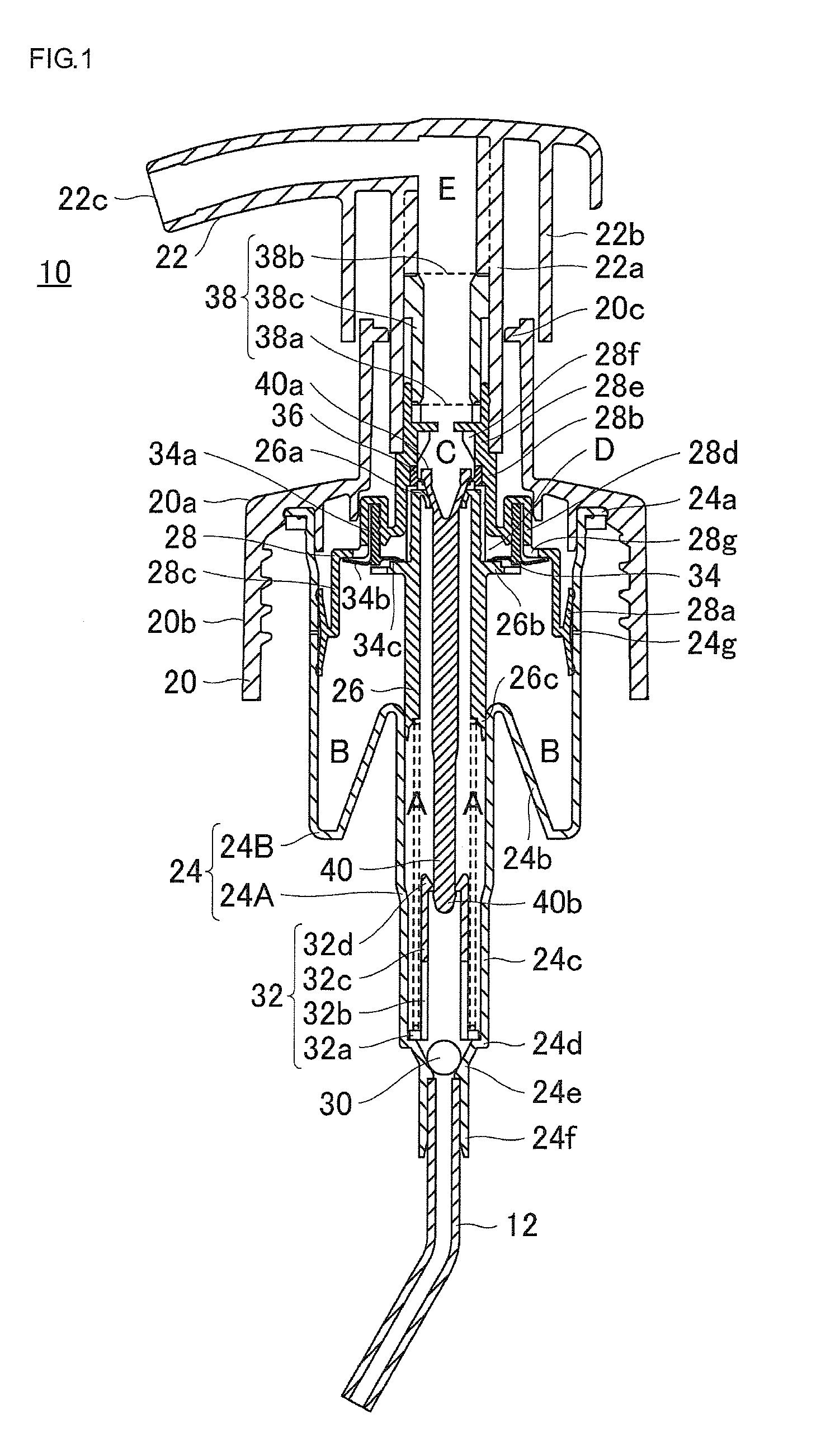
[0010]As a result of intensive study of the problems in the conventional technologies, the inventors have invented a foam-dispensing pump container having a rod-shaped valve body with a latch portion in its upper end for controlling the connection between the air-liquid mixing unit and the liquid chamber. In the lower part of the air-liquid mixing unit, a valve seat portion formed of a flexible member that can come into contact with the outer peripheral face of the latch portion of the rod-shaped valve body is provided in an inwardly projecting manner, and the flexible valve seat portion comes into contact with the rod-shaped valve body before the upper opening end of the liquid chamber comes into contact with the rod-shaped valve body immediately after the nozzle head starts rising. This configuration greatly reduces the backflow of the liquid or air into the air passage and solves the usability problems of the conventional foam-dispensing pump containers.
[0023]a rod-shaped valve body which is disposed in a space formed by the liquid cylinder and the liquid piston, has an upper end penetrating the upper opening end of the liquid piston, has an almost funnel-shaped latch portion at its penetrating upper end, the outer diameter of the latch portion being greater than the diameter of the upper opening end of the liquid piston, the outer peripheral face of the latch portion being able to come into contact with the inner peripheral face of the upper opening end of the liquid piston, and the valve body thereby being able to open and close the connecting portion between the liquid piston and the air-liquid mixing unit;
[0032]The foam-dispensing pump container according to the present invention has the valve seat portion which protrudes inwardly below the air-liquid mixing unit and which is formed of the flexible member that can come into contact with the outer peripheral face of the latch portion of the rod-shaped valve body, and immediately after the nozzle head starts rising, the flexible valve seat portion comes into contact with the rod-shaped valve body before the upper opening end of the liquid chamber comes into contact with the rod-shaped valve body, thereby significantly reducing a backflow of the foam or liquid into the air passage, and consequently improving the usability of the foam-dispensing pump container.

Problems solved by technology

The liquid or foam flowing into the air passage dries and solidifies, and narrows or blocks the flow path, causing problems concerning usability of the foam-dispensing pump container, such as lower foam quality caused by a reduction in the amount of air that can be supplied to the air-liquid mixing chamber, or an increased force required to push down the pump.

Method used


Image

  • Foam-Dispensing Pump Container
  • Foam-Dispensing Pump Container
  • Foam-Dispensing Pump Container

Examples


Embodiment Construction

[0037]A preferred embodiment of the present invention will be described below with reference to the drawings.

Configuration of the Foam-Dispensing Pump Container

[0038]A foam-dispensing pump container in this embodiment includes a container body containing a liquid, a dispensing pump body detachably mounted in an opening in the upper end of the container body, and a tubular body connected to the dispensing pump body and extending into the container body.

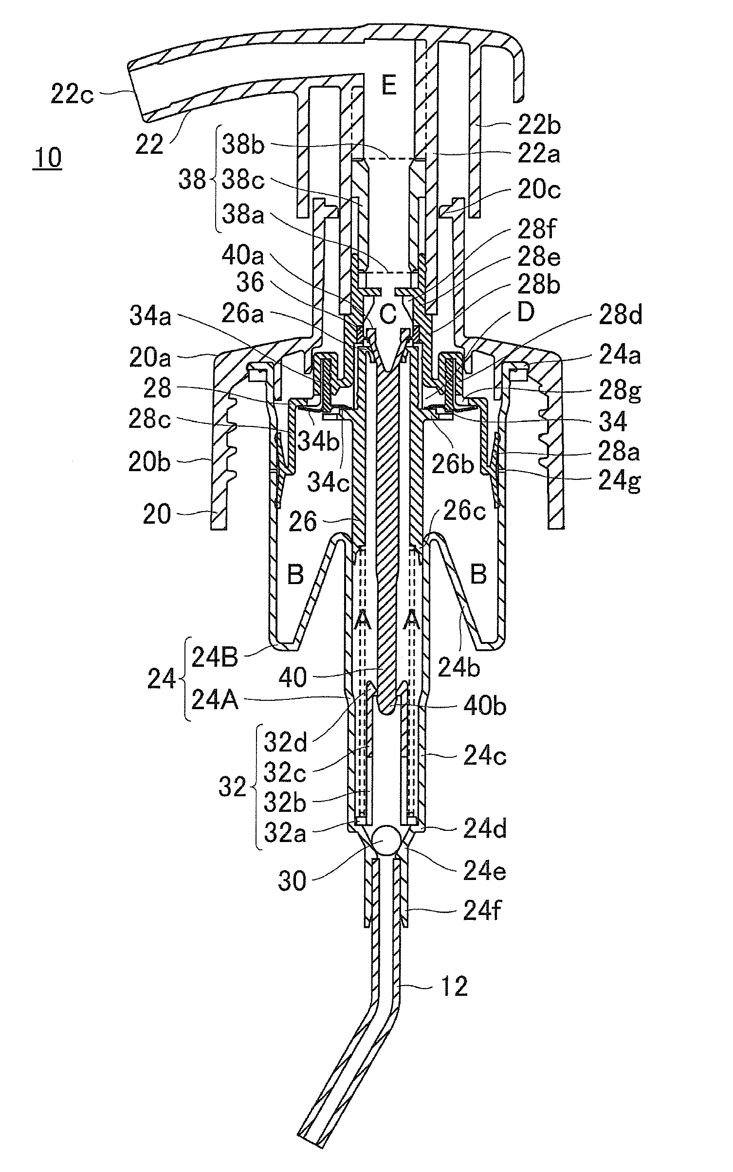
[0039]FIG. 1 shows a front sectional view of the dispensing pump body 10 of the dispensing container according to the embodiment of the present invention, when a nozzle head is in its highest position.

[0040]A skirt base cap portion 20 disposed in the lower part of the dispensing pump body 10 in this embodiment has a female thread formed in its inner peripheral face. The opening of the container body (not shown) containing the foamable liquid has a male thread formed in its outer peripheral face. The dispensing pump body 10 is detachabl...


PUM


Abstract

The foam-dispensing pump container according to the present invention has the valve seat portion which protrudes inwardly below the air-liquid mixing unit and which is formed of the flexible member that can come into contact with the outer peripheral face of the latch portion of the rod-shaped valve body, and immediately after the nozzle head starts rising, the flexible valve seat portion comes into contact with the rod-shaped valve body before the upper opening end of the liquid chamber comes into contact with the rod-shaped valve body, thereby significantly reducing a backflow of the foam or liquid into the air passage, and consequently improving the usability of the foam-dispensing pump container.

Description

RELATED APPLICATIONS[0001]This application claims the priority of Japanese Patent Application No. 2011-062181 filed on Mar. 22, 2011, which is incorporated herein by reference.BACKGROUND OF THE INVENTION[0002]1. Field of the Invention[0003]The present invention relates to foam-dispensing pump containers for discharging, from a foam discharge opening, foam produced by mixing a foamable liquid in the container body and air when a nozzle head is pushed down, and more specifically, to an improvement for preventing usability from being degraded by the liquid or foam flowing backward into the pump after foam is discharged.[0004]2. Description of the Related Art[0005]A variety of configurations have been conventionally proposed for foam-dispensing pump containers that produce foam by mixing a foamable liquid contained in the container body and air drawn into the container from the outside and that discharge the foam from the container to the outside through a foam passage inside a nozzle h...

Claims


Application Information

Patent Timeline
IPC IPC(8): B67D7/76
CPCB05B11/0064B05B11/3087B05B11/3047B05B7/0037B05B11/1047B05B11/1087B65D47/00B05B11/00B65D83/00
Inventor UEHIRA, SHOUJISAITO, DAISUKE
Owner DAIWA CAN
Learn More