Oil Flow Control Structure for Grease Gun

a technology of oil flow control and grease gun, which is applied in the direction of manual lubrication, instruments, machines/engines, etc., can solve the problems of difficult production, high cost, and large components, and achieve the effects of easy assembly, simple structure and easy production

Active Publication Date: 2012-09-27
SUCTION IND
View PDF14 Cites 12 Cited by
  • Summary
  • Abstract
  • Description
  • Claims
  • Application Information

AI Technical Summary

Benefits of technology

[0006]In view of the shortcomings of the prior art, the inventor(s) of the present invention based on years of experience in the related industry to conduct extensive researches and experiments, a...

Problems solved by technology

However, it may need enormous components.
The processing procedure is also complica...

Method used


Image

  • Oil Flow Control Structure for Grease Gun
  • Oil Flow Control Structure for Grease Gun
  • Oil Flow Control Structure for Grease Gun

Examples


Embodiment Construction

[0020]The foregoing and other technical characteristics of the present invention will become apparent with the detailed description of the preferred embodiments and the illustration of the related drawings.

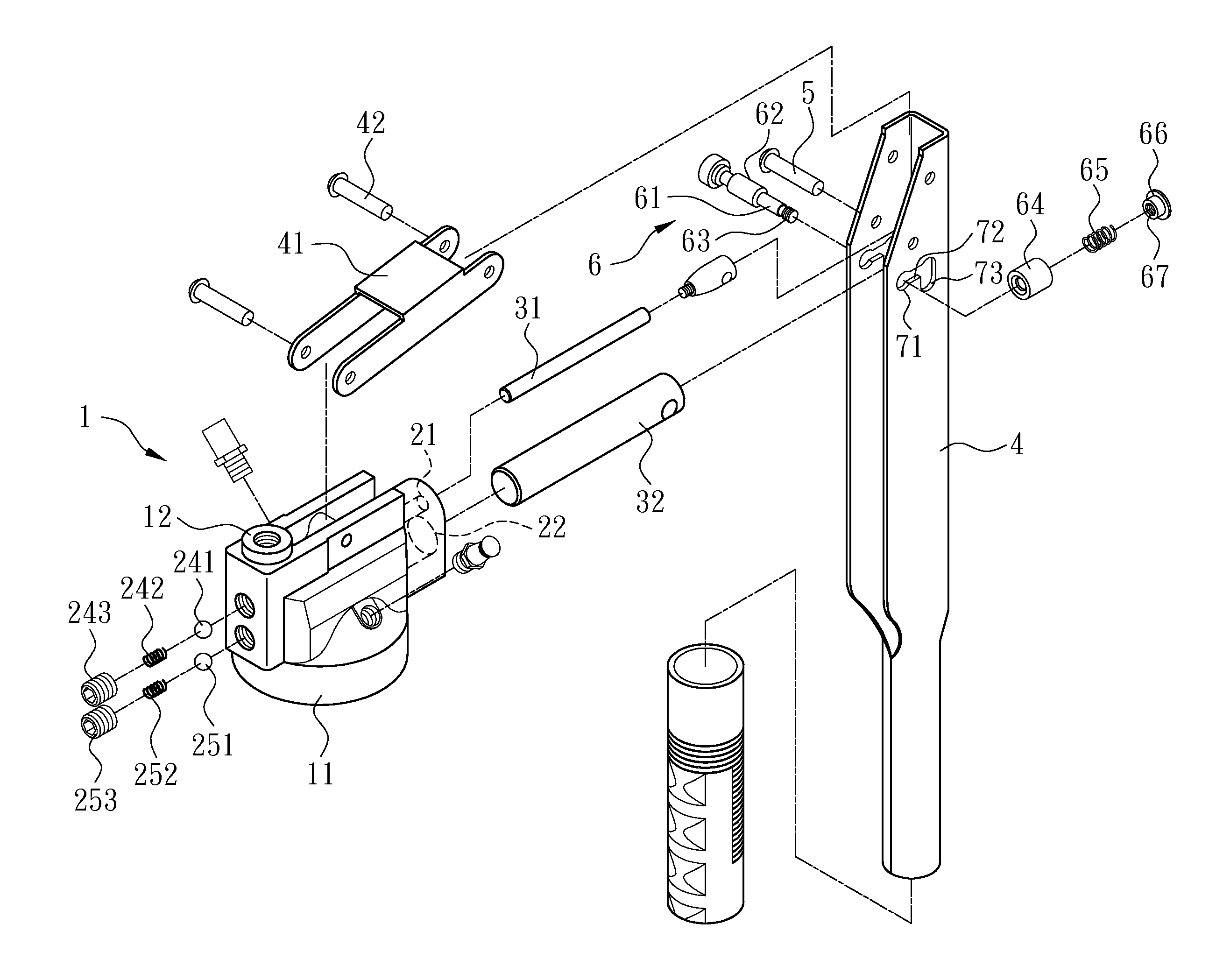
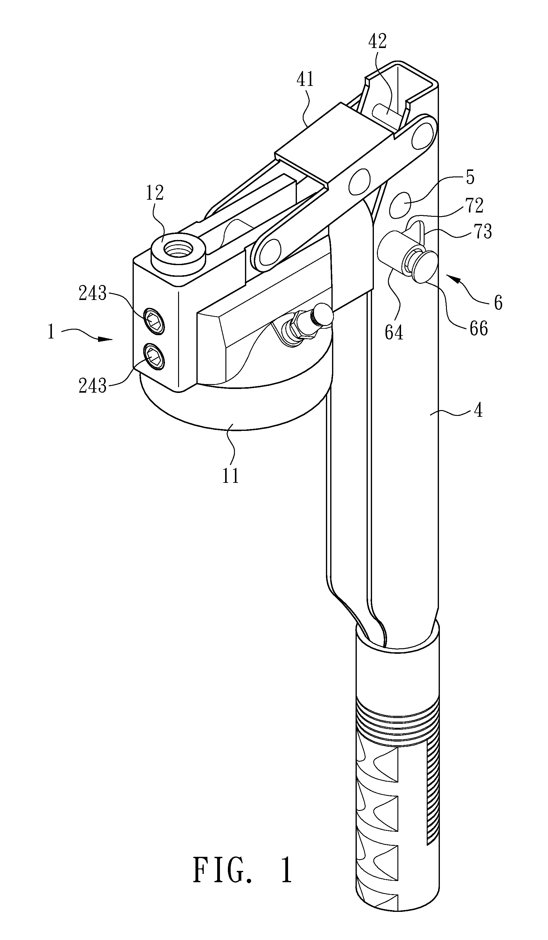
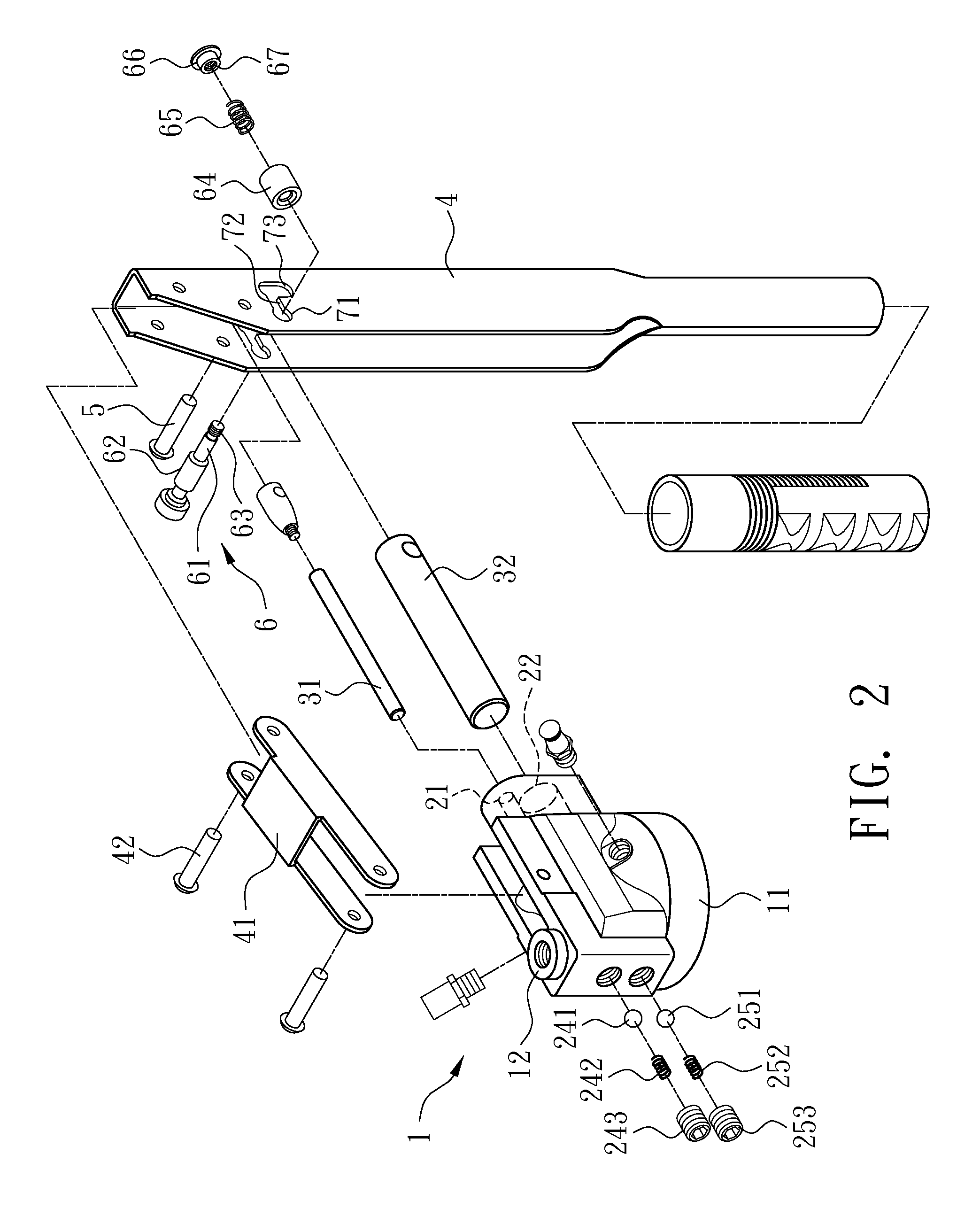
[0021]With reference to FIG. 1 to FIG. 7, a grease gun in accordance with the invention has a hollow main body 1. Opposite side ends of the main body 1 are respectively opened with an inflow end 11 and an outflow end 12 so that a grease barrel 8 at an outside is connected to the inflow end 11 to allow grease flowing into the main body 1. A high pressure passage 21 and a low pressure passage 22, in which its inner diameter is greater than the high pressure passage 21, are disposed between the inflow end 11 and the outflow end 12. One ends of the two passages are respectively disposed with a high pressure outflow port 212 and a low pressure outflow port 222 communicating with the outflow end 12, and a side of the two passages is respectively disposed with a first inflow port 211 and...


PUM


Abstract

An oil flow control structure for grease gun has a hollow main body. An inflow end and an outflow end are respectively disposed at two sides of the main body. A high pressure passage and a low pressure passage, in which its inner diameter is larger than the high pressure passage, are disposed between the inflow end and the outflow end. A first pumping rod and a second pumping rod are respectively disposed in the two passages. The first pumping rod is pivoted to a pressing stem. The second pumping rod is pivoted to the pressing stem through a switching mechanism. The switching mechanism can regulate a pivot position of the second pumping rod relative to the pressing stem so that an initial position of the second pumping rod performing piston motion in the low pressure passage can be changed to seal or open the second inflow port.

Description

BACKGROUND OF THE INVENTION[0001]1. Field of the Invention[0002]The present invention relates to a grease gun, and more particularly to an oil flow control structure for grease gun that regulates outlet pressure according to user demands.[0003]2. Description of the Related Art[0004]As shown in FIG. 8 and FIG. 9, a structure of grease gun having dual-pumping rods is disclosed. A high pressure passage 21B and a low pressure passage 22B are disposed in a main body 1B. A first pumping rod 31B and a second pumping rod 32B are respectively disposed in the high pressure passage 21B and the second pressure passage 22B. The first pumping rod 31B and the second pumping 32B can perform piston motions along an axis of the rod to push grease within the high pressure passage 21B and the low pressure passage 22B. In addition, a drainage portion 9 is disposed between the low pressure passage 22B and the inflow end 11B. The drainage portion 9 comprises a split-flow hole 91 and a slot way 92 circular...

Claims


Application Information

Patent Timeline
IPC IPC(8): G01F11/00
CPCF16N13/08F16N3/12
Inventor KUO, WEN-I
Owner SUCTION IND
Why Eureka
Try Eureka