

Device, head mounted display, control method of device and control method of head mounted display
a technology of head mounted display and control method, which is applied in the direction of portable computers, instruments, computing, etc., can solve the problems of deteriorating image quality, requiring less power consumption, and unable to view a beautiful image in the environment without sufficient outdoor light, so as to achieve the effect of suppressing power consumption and reducing the quality of displayed images
- Summary
- Abstract
- Description
- Claims
- Application Information
AI Technical Summary
Benefits of technology
Problems solved by technology
Method used
Image

Examples
first embodiment
A. First Embodiment
A-1. Device Configuration
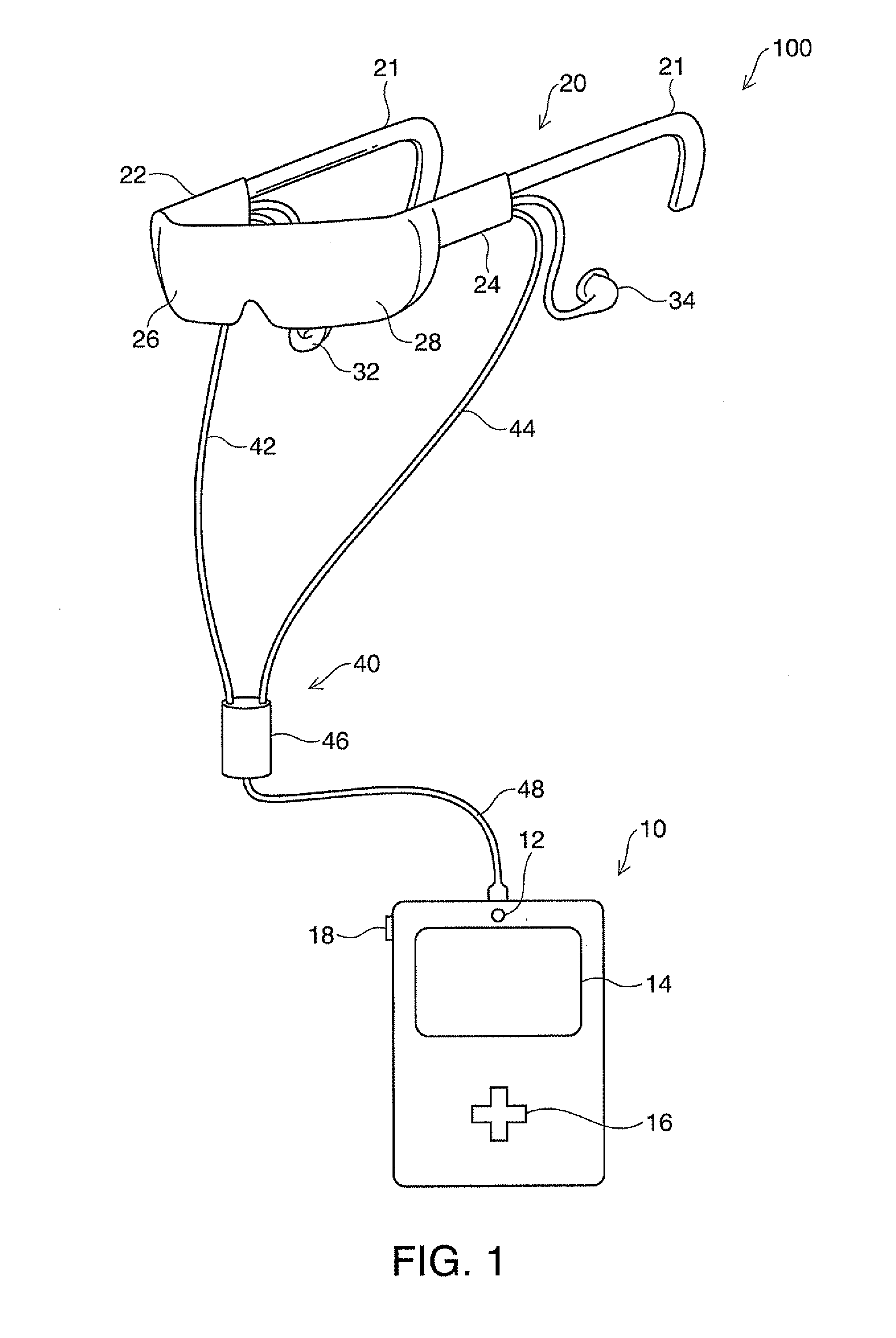
[0077]FIG. 1 is an explanatory diagram showing an outer configuration of a head mounted display 100 in the first embodiment of the invention. The head mounted display 100 is a display mounted on a head and also called an HMD. The head mounted display 100 of the embodiment is an optically transmissive head mounted display by which a user can visually recognize a virtual image and directly visually recognize an outside view.
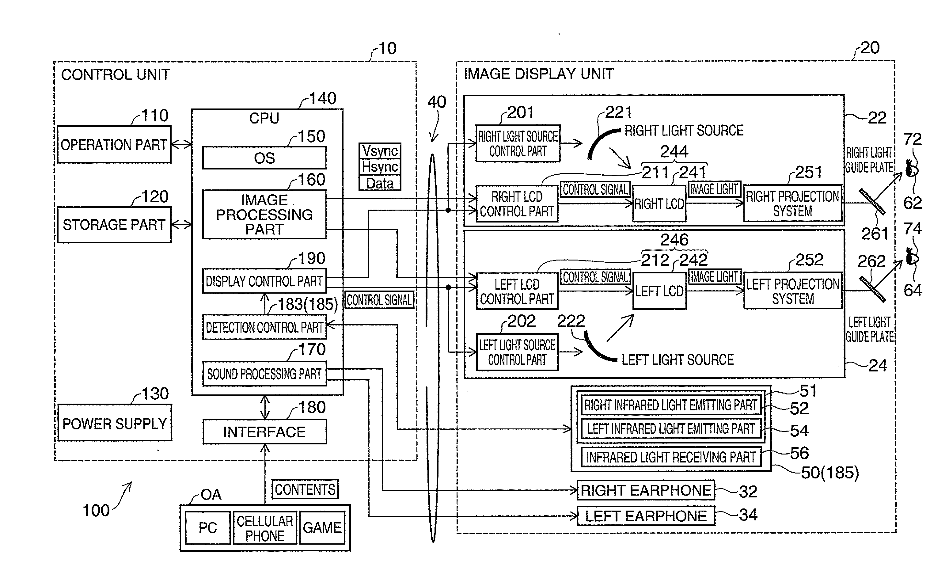
[0078]The head mounted display 100 includes an image display unit 20 that allows the user to visually recognize a virtual image when the display is mounted on the head of the user, and a control unit (controller) 10 that controls the image display unit 20.
[0079]The image display unit 20 is a mounted body mounted on the head of the user and has an eyeglasses shape in the embodiment. The image display unit 20 has ear-fit parts 21 that function as temples, and a right optical panel 26 and a left optical panel 28 located in f...
second embodiment
B. Second Embodiment
[0123]FIG. 6 is a flowchart showing a flow of control processing of the head mounted display 100 in the second embodiment. The head mounted display 100 in the second embodiment is adapted to be operated by the user using eyelids without using hands. The control processing is processing by the head mounted display 100 of performing control in response to the operation using the eyelids of the user.
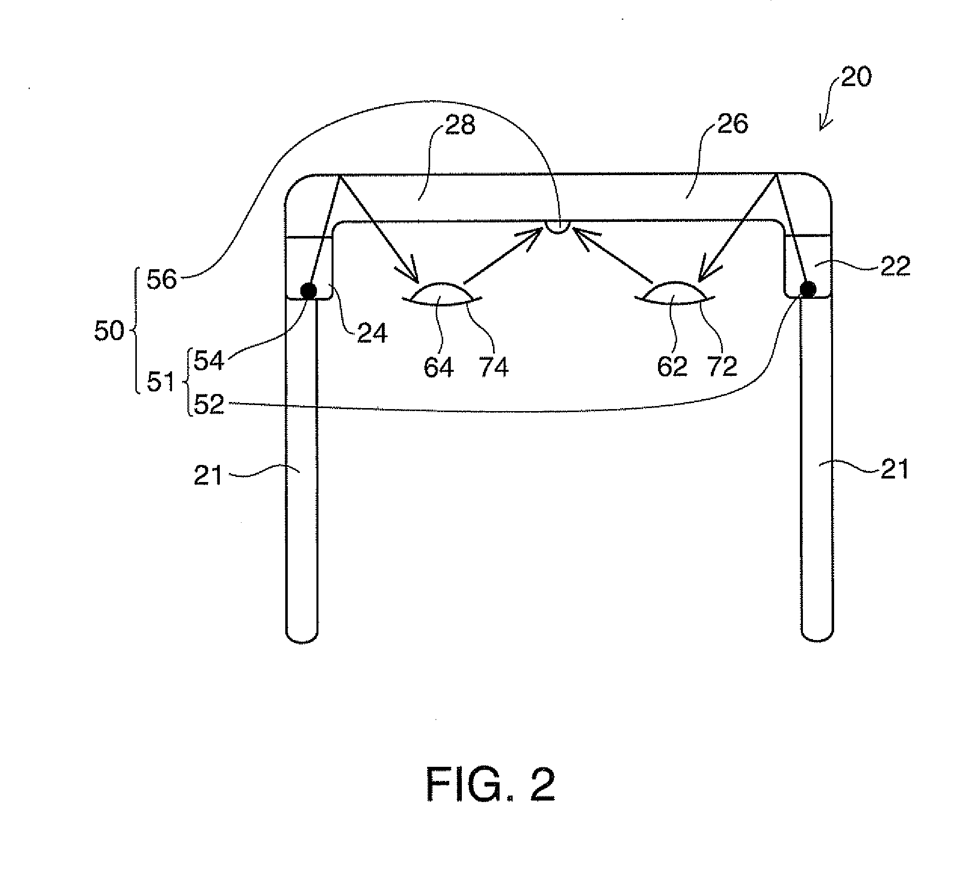
[0124]In the control processing of the head mounted display 100, the detection part 185 detects opened and closed states of the right eyelid 72 (FIG. 2) of the right eye 62 and the left eyelid 74 of the left eye 64 (step S510). FIGS. 7A and 7B are explanatory diagrams showing relationships between time and opened and closed states of eye lids in the second embodiment. FIG. 7A shows an example of a detected open / close signal ES1 representing the opened and closed states of the right eyelid 72 (or the left eyelid 74) in the respective times detected by the infrared sensor ...
modified example 1
C1. Modified Example 1
[0140]The configurations of the head mounted display 100 in the embodiments are just examples and various changes can be made. In the first embodiment, when the detection part 185 detects the eyelids of the user kept closed in the predetermined time, the part determines the user is asleep. However, the user may just close the eyelids, not sleep or may half close the eyes. Accordingly, the display control part 190 may allow the image display unit 20 to display a message of power-saving transition immediately before the power-saving transition. Further, at the same time, the sound processing part 170 gives a message of power-saving transition in sound. Note that the message of power-saving transition may be given only by display of the display control part 190 or sound of the sound processing part 170. If the detection part 185 detects the eyelids of the user opened after notification of the power-saving transition to performance of the power-saving transition, t...
PUM
 Abstract
Description
Claims
Application Information