Extended Source Wavefront Sensor through Optical Correlation

a wavefront sensor and optical correlation technology, applied in the field of optics, can solve problems such as not being well suited to operate with extended sources

Inactive Publication Date: 2012-09-27
THE UNITED STATES OF AMERICA AS REPRESENTED BY THE SECRETARY OF THE NAVY
View PDF1 Cites 14 Cited by
  • Summary
  • Abstract
  • Description
  • Claims
  • Application Information

AI Technical Summary

Problems solved by technology

There are a variety of wavefront sensors, including interferometric sensors, lenslet arrays and wavefront curvature sensors, but they are not well suited to operate with extended sources and are typically used for point sources only.

Method used


Image

  • Extended Source Wavefront Sensor through Optical Correlation
  • Extended Source Wavefront Sensor through Optical Correlation
  • Extended Source Wavefront Sensor through Optical Correlation

Examples


Embodiment Construction

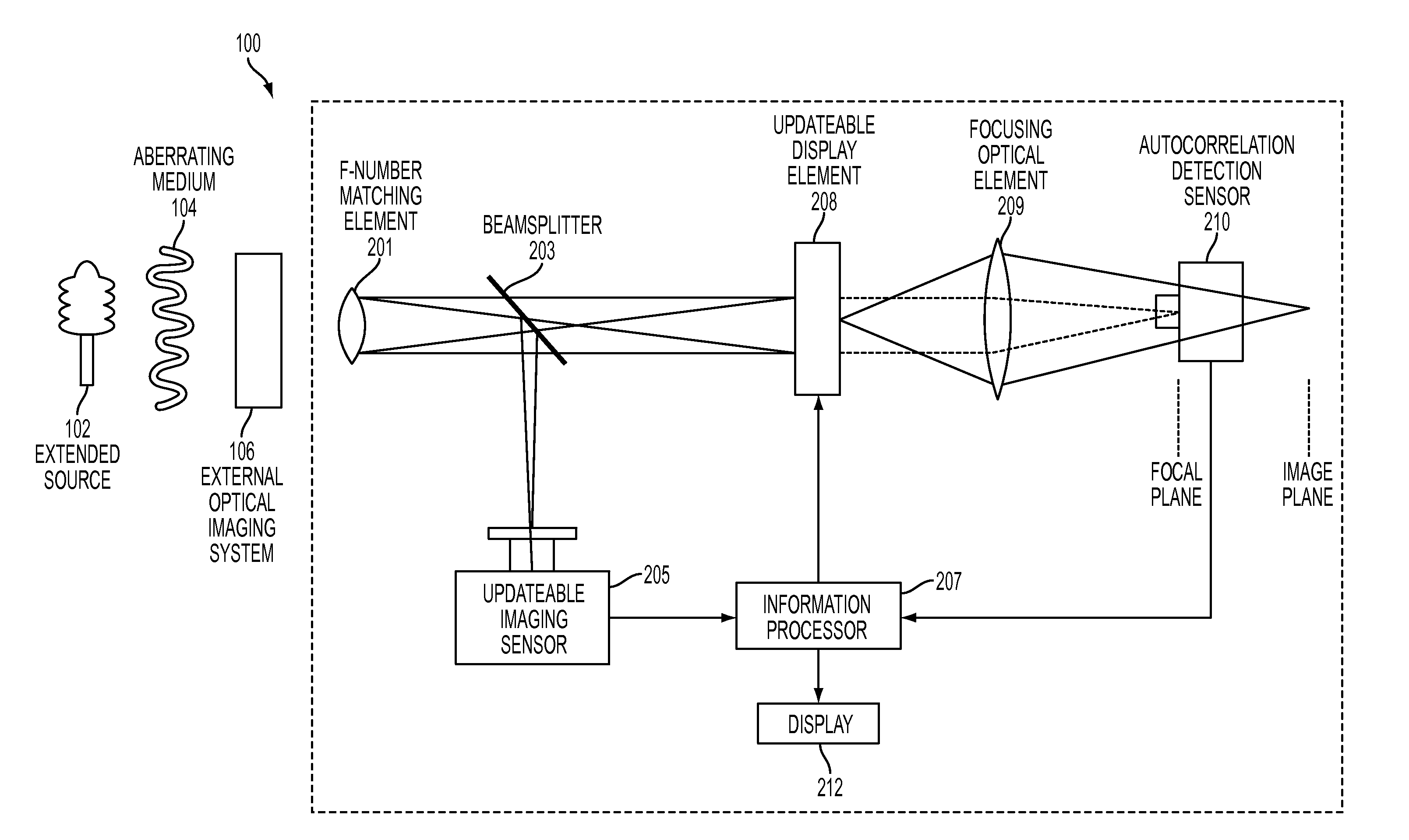
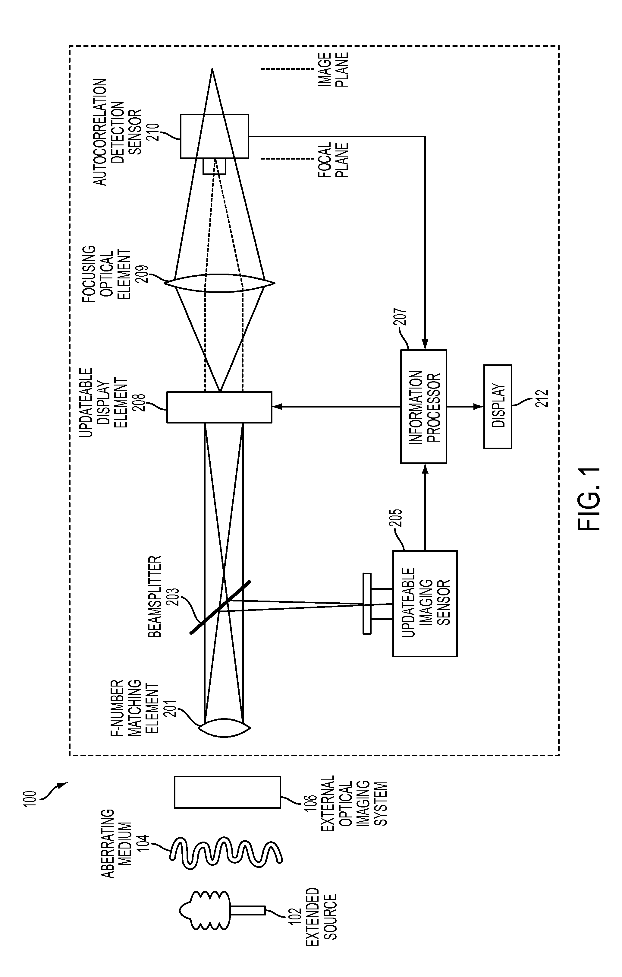
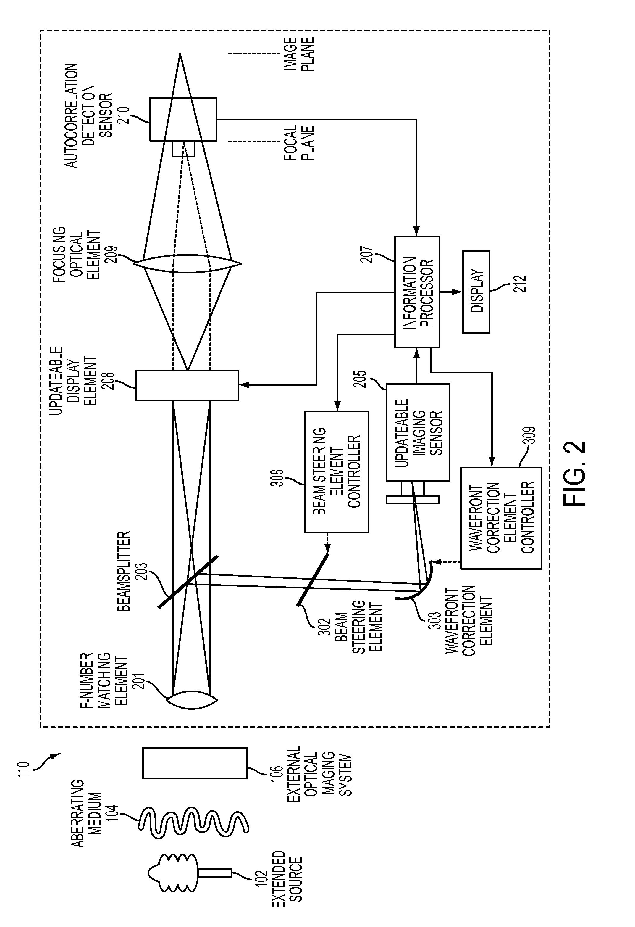
[0019]The principle of this patent is embodied as an extended source wavefront sensing system that uses two optically correlated images of a scene and the Fourier transform capabilities of a focusing optical element. Optical energy from a scene is modulated by a previously recorded image of the scene and their autocorrelation is thus measured. As time evolves, any changes in the scene, platform position or the media that the optical energy passes through, will result in a changes in the incoming optical energy with respect to the previously recorded image and be observed in the autocorrelation. The autocorrelation is measured as a displacement on the autocorrelation detection sensor. Changes in the global tip and tilt, or higher order aberrations, of the light energy entering the system will cause a shift in the central peak of the light on the autocorrelation detection sensor. This peak shift can be detected by centroid detection or other means, and will indicate the wavefront tip / ...


PUM


Abstract

An atmospheric aberration sensor that uses two optically correlated images of a scene and the Fourier transform capabilities of a lens or other focusing element. The sensor receives light via an f-number matching element from a scene or from an external optical system and transmits it through a focusing optical element to an updateable display element such as a spatial light modulator or micro mirror array, which modulates the real time image from the focusing element with previous template image of the same extended scene. The modulated image is focused onto an autocorrelation detection sensor, which detects a change in centroid position corresponding to a change of the tip / tilt in the optical path. This peak shift is detected by centroid detection and corresponds to the magnitude of global wavefront tip / tilt. With a lenslet array and detector array, the system can also measure local tip / tilt and higher order aberrations.

Description

CROSS-REFERENCE TO RELATED APPLICATIONS[0001]This application is a continuation in part of U.S. application Ser. No. 13 / 351,821, filed on Jan. 17, 2012, which is a non-provisional under 35 USC 119(e) of and claims the benefit of U.S. Provisional Application 61 / 432,752 filed on Jan. 14, 2011. The entire disclosure of each of these references is incorporated herein by reference.BACKGROUND[0002]1. Technical Field[0003]The invention is related to the field of optics, and more specifically, to the field of adaptive optics, active optics, platform and image stabilization for extended source applications such as astronomical, terrestrial, marine, space imaging systems.[0004]2. Related Technology[0005]Adaptive and active optics systems are intended to measure and compensate, in near real time, aberrations introduced in an optical wavefront as it passes through a medium, or from jitter induced by motion in a platform. In these systems, a wavefront sensor is employed to measure the phase fron...

Claims


Application Information

Patent Timeline
Patent Type & Authority Applications(United States)
IPC IPC(8): H04N7/18G06K9/64H05G1/64
CPCG01J9/00G06K9/741G02B26/06G06V10/89
Inventor RESTAINO, SERGIO R.TEARE, SCOTT W.ANDREWS, JONATHAN R.
Owner THE UNITED STATES OF AMERICA AS REPRESENTED BY THE SECRETARY OF THE NAVY
Why Eureka
Try Eureka