Gas measurement module for use in therapeutic settings comprising reflective scanning microspectrometer

a technology of gas measurement module and microspectrometer, which is applied in the direction of optical radiation measurement, instruments, spectrometry/spectrophotometry/monochromator, etc., can solve the significant limitation of not being able to operate in flameless mode, low nox emissions of flameless combustion, and cold instability. , to achieve the effect of low nox emissions

Active Publication Date: 2012-09-27
KONINKLIJKE PHILIPS ELECTRONICS NV
View PDF12 Cites 6 Cited by
  • Summary
  • Abstract
  • Description
  • Claims
  • Application Information

AI Technical Summary

Benefits of technology

[0031]Furthermore, the burner of the invention provides that the primary combustion is broken down into primary sub-combustions in which the combustion ratio is kept constant but for which the primary combustible gas and the primary comburent air are injected and mixed at different distances from the combustion head. Thereby, although the combustion ratio is kept unaltered, the flame is further diluted with particularly advantageous effects for reducing the formation of the NOx.
[0032]Due to the geometry of the combustion head or diffuser and to the configuration of the holes for injecting the secondary air (partially comburent in the secondary combustion and partially in the tertiary combustion) and the tertiary air (comburent in the tertiary combustion) the flame generated by the burner is particularly lean and compact. The holes of the secondary air are advantageously configured so as to create a “swirled” and compact flame.
[0033]A particular advantage for the type of process to be achieved is that the burner does not require differentiating the combustion technique according to the temperature of the combustion chamber to reduce the NOx emissions. Indeed, the burner is made to operate at temperatures about the temperature of spontaneous ignition of the fuel, hence it is impossible to use combustion techniques which have as their main prerogative a chamber temperature always higher than the one of spontaneous ignition of the combustible (flameless combustion). Advantageously, for the same reason the burner of the invention does not require a double inlet for the comburent air or for the combustible gas.
[0034]Moreover, as is known, most flameless burners on the market require a higher pressure of the combustible gas with respect to the one of traditional burners while the burner of the invention succeeds in obtaining excellent performances with the same air and gas pressures of a traditional burner.
[0035]The fuel and the combustion air are injected into the combustion chamber at such a speed whereby a high recirculation of the burnt gases is obtained. In particular, the speed of the tertiary air and of the secondary gas (fuel in the tertiary combustion) are crucial for obtaining a strong mixing with the burnt gases and consequently decreasing the percentage of oxygen in the combustion.
[0036]The main innovation of the burner of the invention concerns the fact that by simultaneously using the “fuel staging”, heavily diluting the flame and recirculating the flue gases, the NOx emission are always very low at any chamber temperature and the burner succeeds in entering an operating range in which the flameless combustion is automatically generated.

Problems solved by technology

However, the drawback of the burners which use these techniques is the cold instability, i.e. below the spontaneous ignition temperature as the two combustions are fed by unbalanced reagents, one with air in excess and the other with gas in excess.
The burners which use flameless combustion have significantly low NOx emissions but have the significant limitation of not being able to operate in flameless mode below the temperature of spontaneous ignition of the fuel.
The burners which operate with the mentioned combustion techniques have significant advantages when the chamber temperature is high but have significant limitations when the temperature is below or about the temperature of spontaneous ignition of the fuel.

Method used


Image

  • Gas measurement module for use in therapeutic settings comprising reflective scanning microspectrometer
  • Gas measurement module for use in therapeutic settings comprising reflective scanning microspectrometer
  • Gas measurement module for use in therapeutic settings comprising reflective scanning microspectrometer

Examples


Embodiment Construction

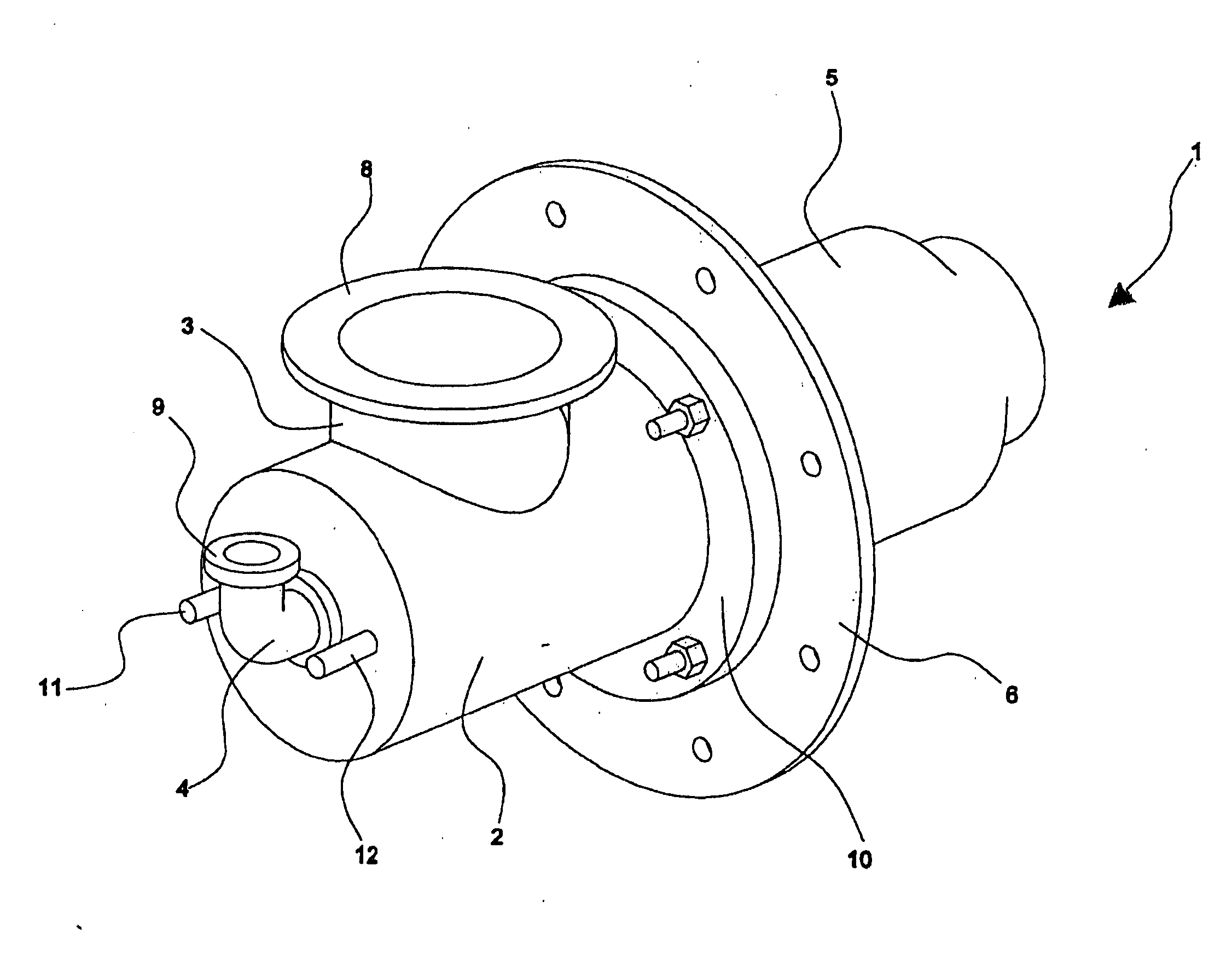
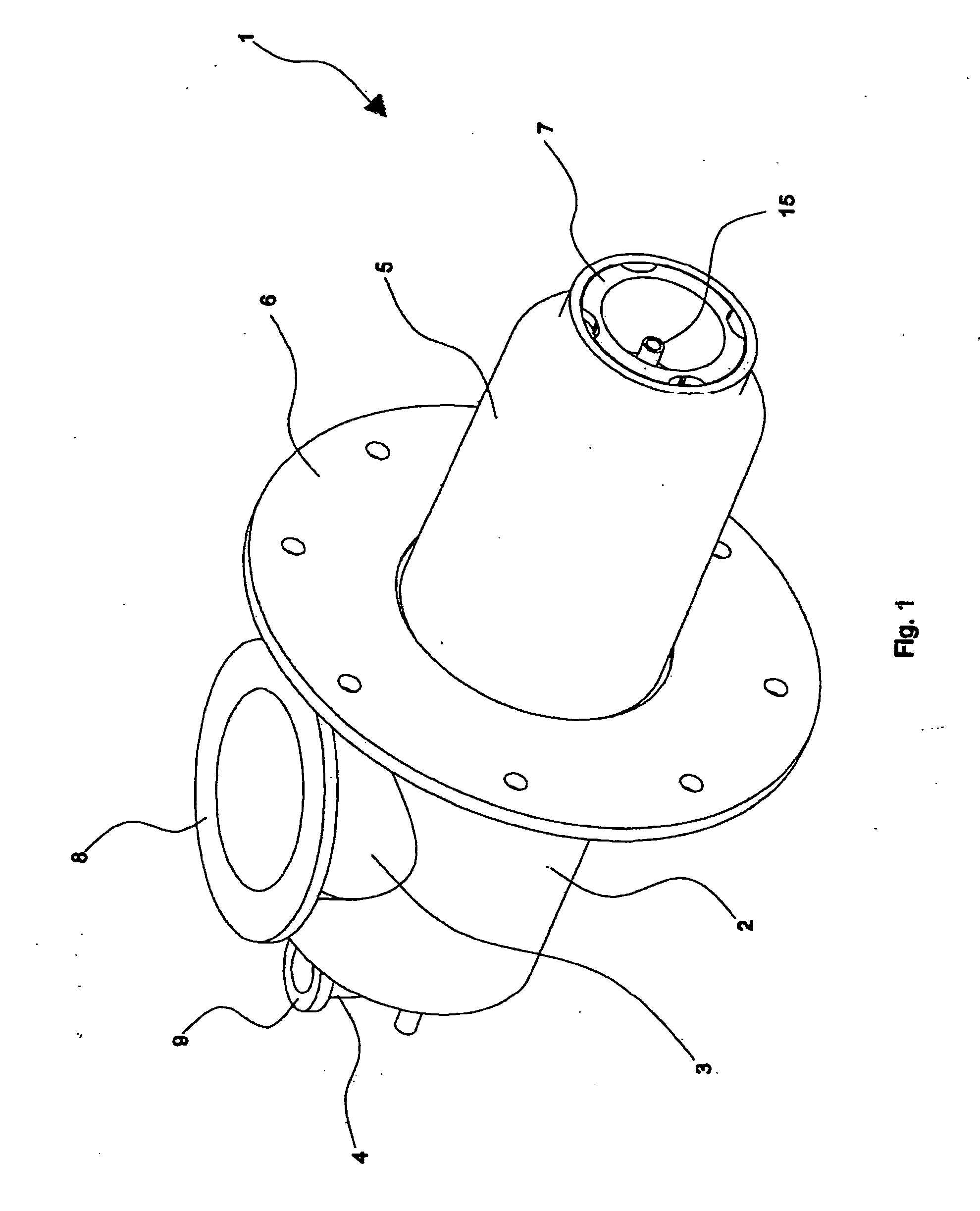
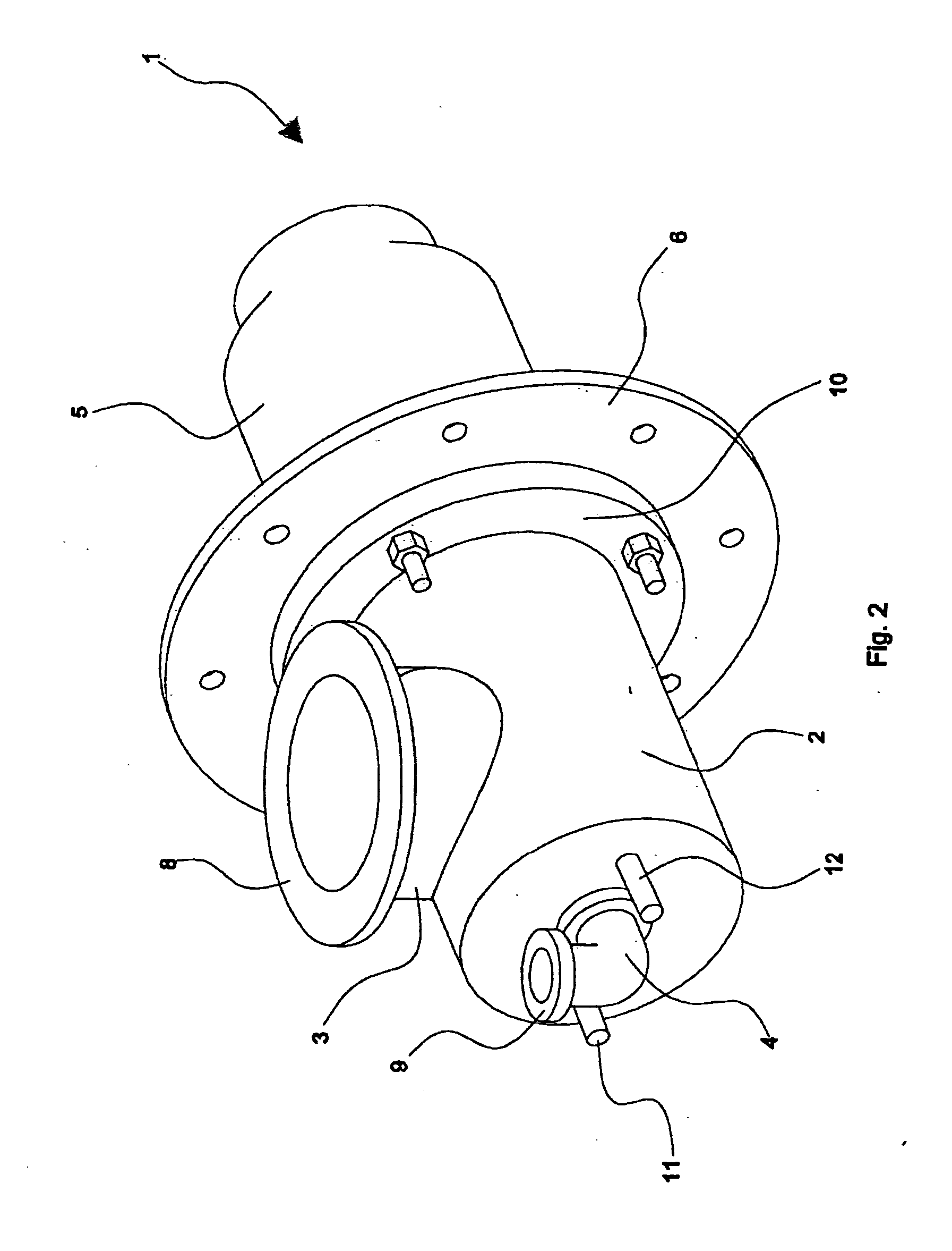
[0057]With reference to the figures, a preferred embodiment is shown of a burner, globally indicated by numeral 1, adapted to achieve a very low NOx emission combustion with high speed flame by using the simultaneous combination of the techniques of “fuel staging”, recirculating flue gases and diluting the flame.

[0058]The burner 1, object of the present invention, defines a longitudinal axis X and comprises:[0059]a main metal holly body, in essence of cylindrical shape, comprising a first longitudinal hollow element 2 connected to and communicating with a second longitudinal tubular element 5 or flame guide tube;[0060]a pipe for feeding the comburent air 3;[0061]a pipe for feeding the combustible gas 4;[0062]a connection flange 6 of the burner to the furnace armour plate;[0063]a connection flange 10 of the first longitudinal hollow element 2 on the connection flange 6;[0064]a cylindrical tubular element 7, preferably made with silicon carbide or other suitable material, accommodated...


PUM

PropertyMeasurementUnit
temperatureaaaaaaaaaa
flame propagation speedaaaaaaaaaa

Abstract

A high speed burner having very low polluting emissions, suitable for the process for heat treatment furnaces of a load in free atmosphere. The burner is capable of creating a compact and lean flame with the peculiarity of keeping the NOx emissions at very low levels at any chamber temperature and at any excess combustion air. The burner requires a single inlet for the comburent air and a single inlet for the combustible gas.

Description

FIELD OF THE INVENTION[0001]The present invention relates to a high speed burner with lean and compact flame capable of obtaining very low NOx emissions while keeping the flame stable at any chamber temperature. The burner implements combustion techniques such as dividing the main combustion into three stages (air and fuel staging), recirculating flue gases and further diluting some reagents.STATE OF THE ART[0002]Over the last years, the market demand concerning a reduction in gas consumption has forced industrial furnace manufacturers to develop their products by taking advantage of the heat of the combustion flue gases for heating the combustion air by means of exchangers. Therefore, the need has been created to develop burners which operate with comburent air pre-heated at a temperature of about 400-550° C. At the same time, the laws on nitrogen monoxide and dioxide emissions have established increasingly restrictive limitations and have forced manufacturers to make burners capab...

Claims


Application Information

Patent Timeline
Patent Type & Authority Applications(United States)
IPC IPC(8): G01N21/35
CPCA61B5/08G01N33/497G01N21/3504A61B5/082G01J5/02G01J5/10G01J5/20G01N21/3563G01N21/3581
Inventor RUSSELL, JAMES TORRANCE
Owner KONINKLIJKE PHILIPS ELECTRONICS NV
Why Eureka
Try Eureka