Switch and switch circuit using the same

a switch circuit and switch technology, applied in the direction of electronic switching, emergency protective arrangements for limiting excess voltage/current, pulse technique, etc., can solve the problems of parasitic diodes formed between the source and the drain, and the inability to take sufficient measures

Active Publication Date: 2012-09-27
SEMICON COMPONENTS IND LLC
View PDF10 Cites 19 Cited by
  • Summary
  • Abstract
  • Description
  • Claims
  • Application Information

AI Technical Summary

Benefits of technology

[0010]Another aspect of the present invention is a switch circuit. The switch circuit which is mounted in a device having a common terminal that allows a terminal of a cable capable of transmitting high-frequency signals and a terminal of a cable dedicated to transmit audio signals to be commonly inserted, and includes a high-frequency-system switch that can switch whether to pass a high-frequency signal, and an audio-system switch that is dedicated to switch whether to pass an audio signal. A signal line from the common terminal branches into two signal lines, which are connected to one end of the high-frequency-system switch and one end of the audio-system switch of a first hierarchy, a signal line from the other end of the high-frequency-

Problems solved by technology

However, if the back-gate terminal and the source terminal are connected, a parasitic diode is formed between the source and the drain.
In general, when switches are ON, sufficient measures are often taken aga

Method used


Image

  • Switch and switch circuit using the same
  • Switch and switch circuit using the same
  • Switch and switch circuit using the same

Examples


first embodiment

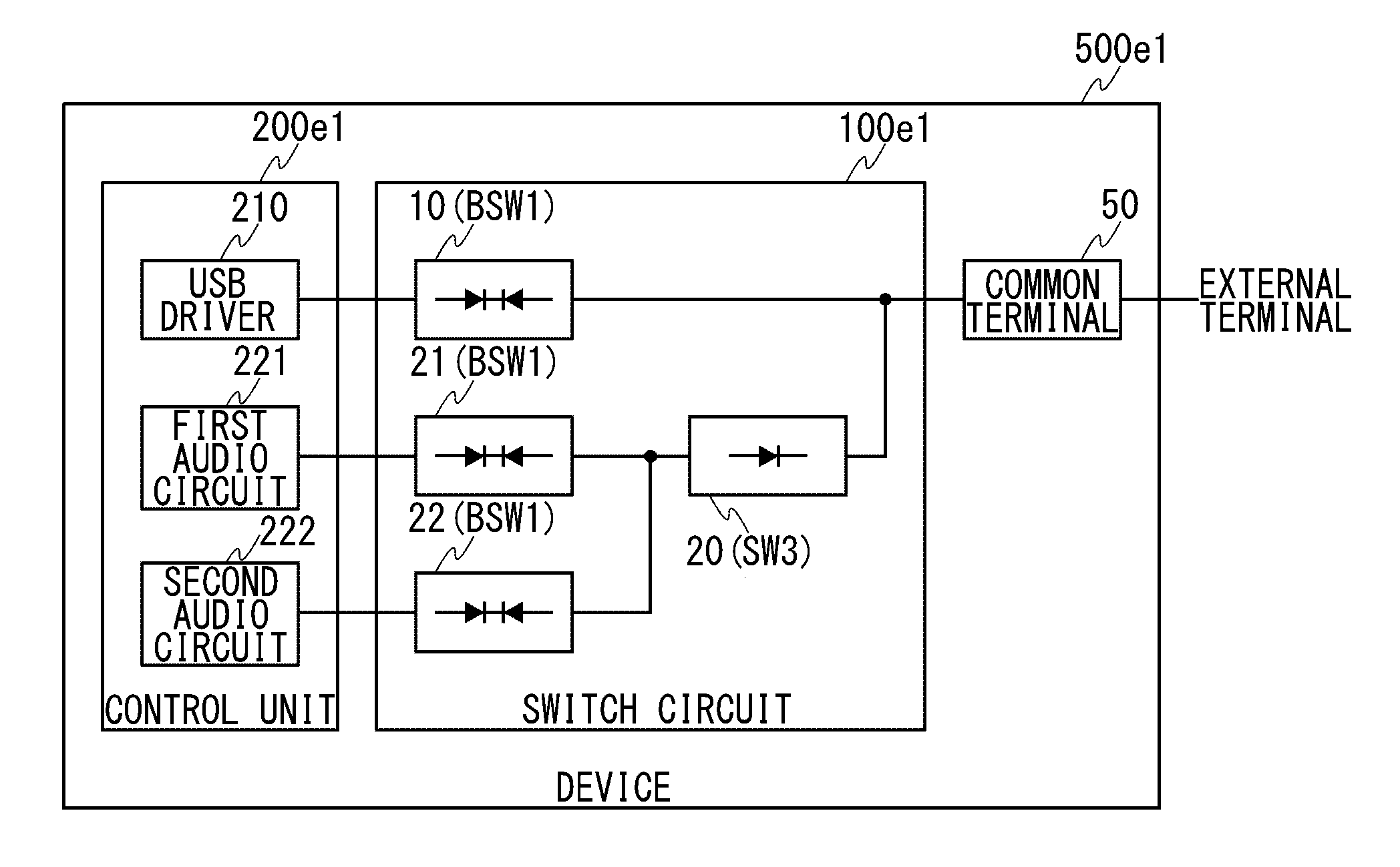
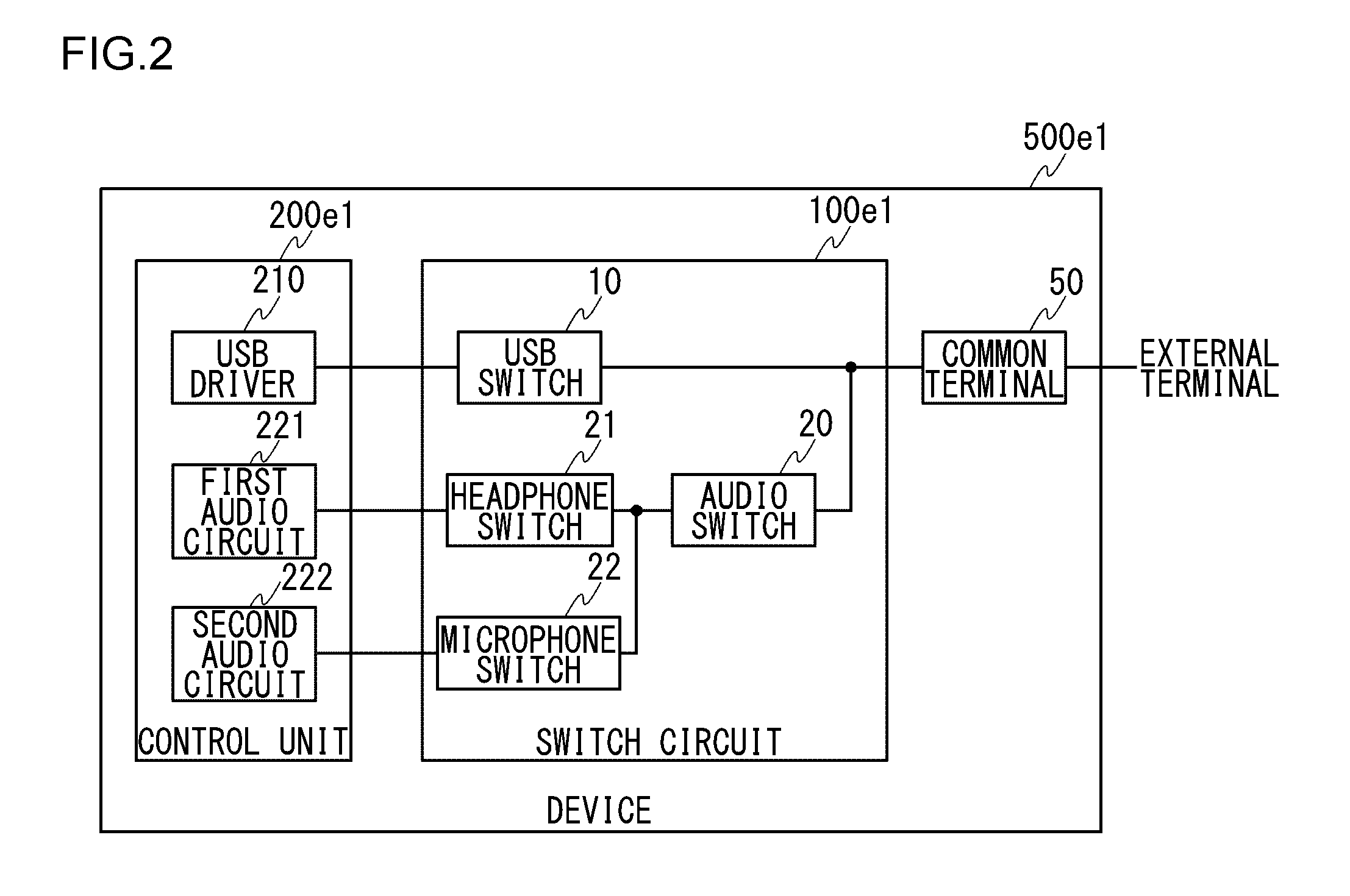
[0033]FIG. 2 is a block diagram for describing a switch circuit 100e1 according to the present invention. The device 500e1 includes a control unit 200e1, the switch circuit 100e1, and a common terminal 50. The control unit 200e1 includes a USB driver 210, a first audio circuit 221, and a second audio circuit 222. The switch circuit 100e1 includes a USB switch 10, an audio switch 20, a headphone switch 21, and a microphone switch 22.

[0034]The common terminal 50 allows a terminal of a USB cable, a terminal of a headphone cable, and a terminal of a microphone cable to be commonly inserted. A signal line from the common terminal 50 branches into two signal lines, which are connected to one end of the USB switch 10 and one end of the audio switch 20 that is a switch of a first hierarchy of the audio-system switch, respectively. A signal line from the other end of the USB switch 10 is connected to the USB driver 210.

[0035]A signal line from the other end of the audio switch 20 of the firs...

second embodiment

[0040]Capacity seen from a signal line for USB in the switch circuit 100e1 or 100e2 according to the first or second embodiment is mostly capacity of the audio switch 20, and thus is rarely influenced even if audio-system switches of the second hierarchy increase. Therefore, even if the number of the audio-system switches of the second hierarchy increases, the necessity of measures against an increase in the load capacity of the audio-system switches of the second hierarchy is low. For example, in order to suppress an increase in the load capacity, the necessity to reduce the sizes of transistors to be used as the switches is low. As long as the sizes of the transistors are not reduced, even if the number of audio-system switches of the second hierarchy increases, the quality of audio signals passing through the audio-system switches is rarely reduced.

[0041]Meanwhile, if two audio-system switches are connected in series, the THD of an audio signal passing through the two audio-syste...


PUM


Abstract

A fourth n-channel MOSFET has a source terminal and a back-gate terminal connected to each other. A switch element is connected between the source terminal of the fourth n-channel MOSFET and a ground potential, and the source terminal of the fourth n-channel MOSFET is made become the ground potential when the fourth n-channel MOSFET is OFF. A protection circuit is provided between a connection node of the source terminal of the fourth n-channel MOSFET and an input terminal of the switch element, and the ground potential so that a negative inflow current from the drain terminal of the fourth n-channel MOSFET caused by electrostatic discharge flows to the ground potential.

Description

[0001]This application is based upon and claims the benefit of priority from the prior Japanese Patent Application No. 2011-066490, filed on Mar. 24, 2011, the entire content is incorporated herein by reference.BACKGROUND OF THE INVENTION[0002]1. Field of the Invention[0003]The present invention relates to a switch for switching a signal having amplitudes on the positive side and the negative side, and a switch circuit using the switch.[0004]2. Description of the Related Art[0005]An analog audio signal has amplitudes on the positive side and the negative side relative to 0 V (ground potential). Therefore, in a switch for switching a signal having amplitudes on the positive side and the negative side like an analog audio signal, symmetry in a pass characteristic between the positive side and the negative side is required. In general, to a gate terminal of a MOSFET (here, an n-channel MOSFET is assumed) that is used as a switch, a high-level voltage (for example, a power supply potent...

Claims


Application Information

Patent Timeline
IPC IPC(8): H02B1/00H02H9/04
CPCH03K17/08142H03K2217/0054H03K17/6874
Inventor YAMADA, KOUICHI
Owner SEMICON COMPONENTS IND LLC
Why Eureka
Try Eureka