Methods of electrical signaling in an ion energy analyzer

a technology of ion energy analyzer and electrical signaling, which is applied in the field of ion energy analysis, can solve problems such as substantive nois

Active Publication Date: 2012-10-04
TOKYO ELECTRON LTD
View PDF12 Cites 8 Cited by
  • Summary
  • Abstract
  • Description
  • Claims
  • Application Information

AI Technical Summary

Benefits of technology

[0012]One other embodiment of the present invention includes an RC circuit for filtering high frequency signal transferred from an ion energy analyzer to an ion energy analyzer controller. The ion energy analyzer for used in determining an ion energy distribution of a plasma within

Problems solved by technology

For example, most known conventional analyzers perturb the processing plasma to an extent that the measurement is no longer characteristic of the conditions prevailing

Method used


Image

  • Methods of electrical signaling in an ion energy analyzer
  • Methods of electrical signaling in an ion energy analyzer
  • Methods of electrical signaling in an ion energy analyzer

Examples


Embodiment Construction

[0041]In the following description, to facilitate a thorough understanding of the invention and for purposes of explanation and not limitation, specific details are set forth, such as a particular geometry of the plasma processing system and various descriptions of the system components. However, it should be understood that the invention may be practiced with other embodiments that depart from these specific details.

[0042]Nonetheless, it should be appreciated that, contained within the description are features which, notwithstanding the inventive nature of the general concepts being explained, are also of an inventive nature.

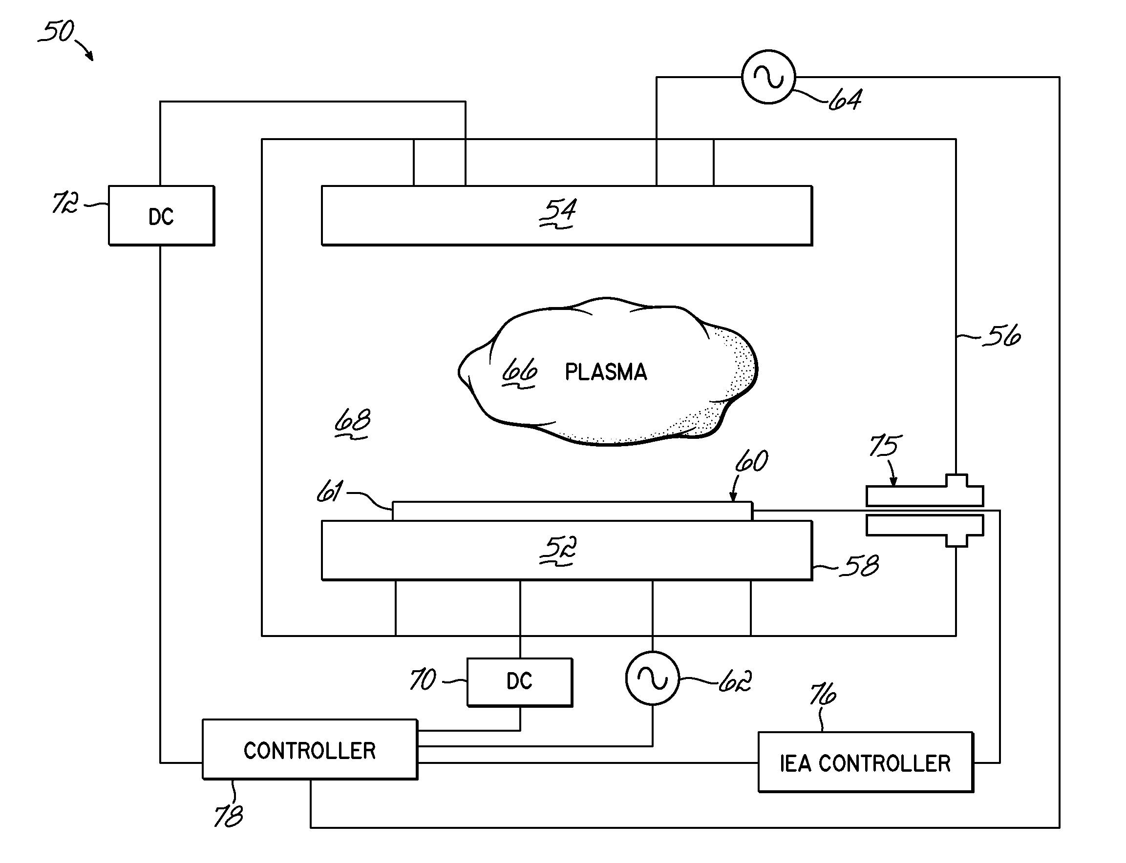
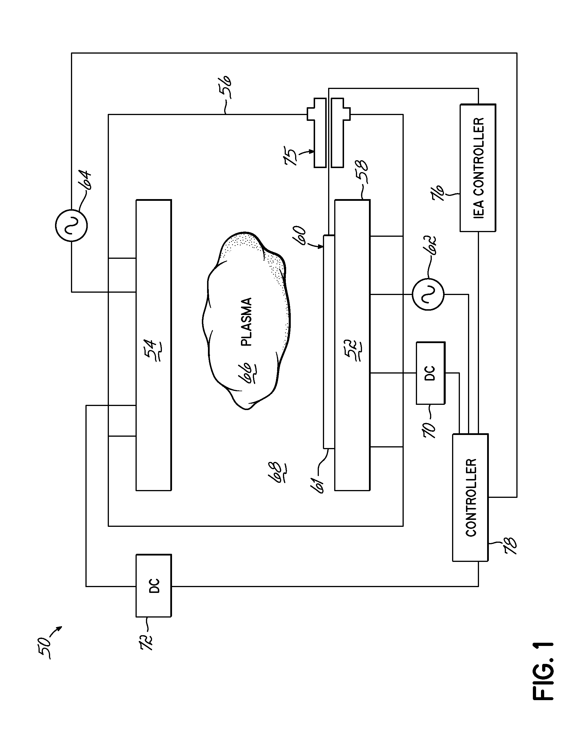
[0043]Referring now to the figures, and in particular to FIG. 1, a simplified schematic of a plasma processing system 50 according to one embodiment of the present invention is shown. The plasma processing system 50 comprises a first electrode 52 and a second electrode 54 disposed on generally opposing sides of a processing chamber 56, wherein the first electro...


PUM

PropertyMeasurementUnit
Lengthaaaaaaaaaa
Distributionaaaaaaaaaa

Abstract

A method of generating a signal representing with an ion energy analyzer for use in determining an ion energy distribution of a plasma. The ion energy analyzer, used for determining an ion energy distribution of a plasma, includes a first grid and a second grid that is spaced away from and electrically isolated from the first grid. The first grid forms a first surface of the ion energy analyzer and is positioned to be exposed to the plasma. The first grid includes a first plurality of openings, which are dimensioned to be less than a Debye length for the plasma. A voltage source and an ion current meter are operably coupled to the second grid, the latter of which is configured to measure an ion flux onto the ion collector and to transmit a signal that represents the measured ion flux. The method includes selectively and variably biasing the second grid relative to the first grid.

Description

[0001]The present application claims the filing benefit of co-pending U.S. Provisional Patent Application No. 61 / 468,187, filed on Mar. 28, 2011, the disclosure of which is hereby incorporated by reference herein in its entirety. The present application is related to co-pending U.S. application Ser. No. ______ (Docket No. TEA-51US1), entitled ION ENERGY ANALYZER; U.S. application Ser. No. ______ (Docket No. TEA-85), entitled ION ENERGY ANALYZER AND METHODS OF MANUFACTURING THE SAME; and International Application No. ______ (Docket No. TEA-51WO), entitled ION ENERGY ANALYZER, METHODS OF ELECTRICAL SIGNALING THEREIN, AND METHODS OF MANUFACTURING AND OPERATING THE SAME. These related, co-pending applications were filed on even date herewith and the disclosure of each is incorporated herein by reference, in its entirety. The present application is also related to commonly assigned U.S. Pat. No. 7,777,179, issued on Aug. 17, 2010, and U.S. Pat. No. 7,875,859, issued on Jan. 25, 2011, the...

Claims


Application Information

Patent Timeline
IPC IPC(8): G01T1/185
CPCH01J37/32935Y10T29/49002H05H1/0081H01J49/488H01J49/04
Inventor FUNK, MERRITTCHEN, LEELANE, BARTONZHAO, JIANPINGSUNDARARAJAN, RADHA
Owner TOKYO ELECTRON LTD
Why Eureka
Try Eureka