Electric charging system

a charging system and electric technology, applied in the direction of battery/cell propulsion, engine-driven generator propulsion, transportation and packaging, etc., can solve the problems of insulation failure and erroneous determination of insulation failur

a charging system and electric technology, applied in the direction of battery/cell propulsion, engine-driven generator propulsion, transportation and packaging, etc., can solve the problems of insulation failure and erroneous determination of insulation failur

US20120249069A1Active Publication Date: 2012-10-04SUBARU CORP

Image

  • Electric charging system
  • Electric charging system
  • Electric charging system

Examples


Embodiment Construction

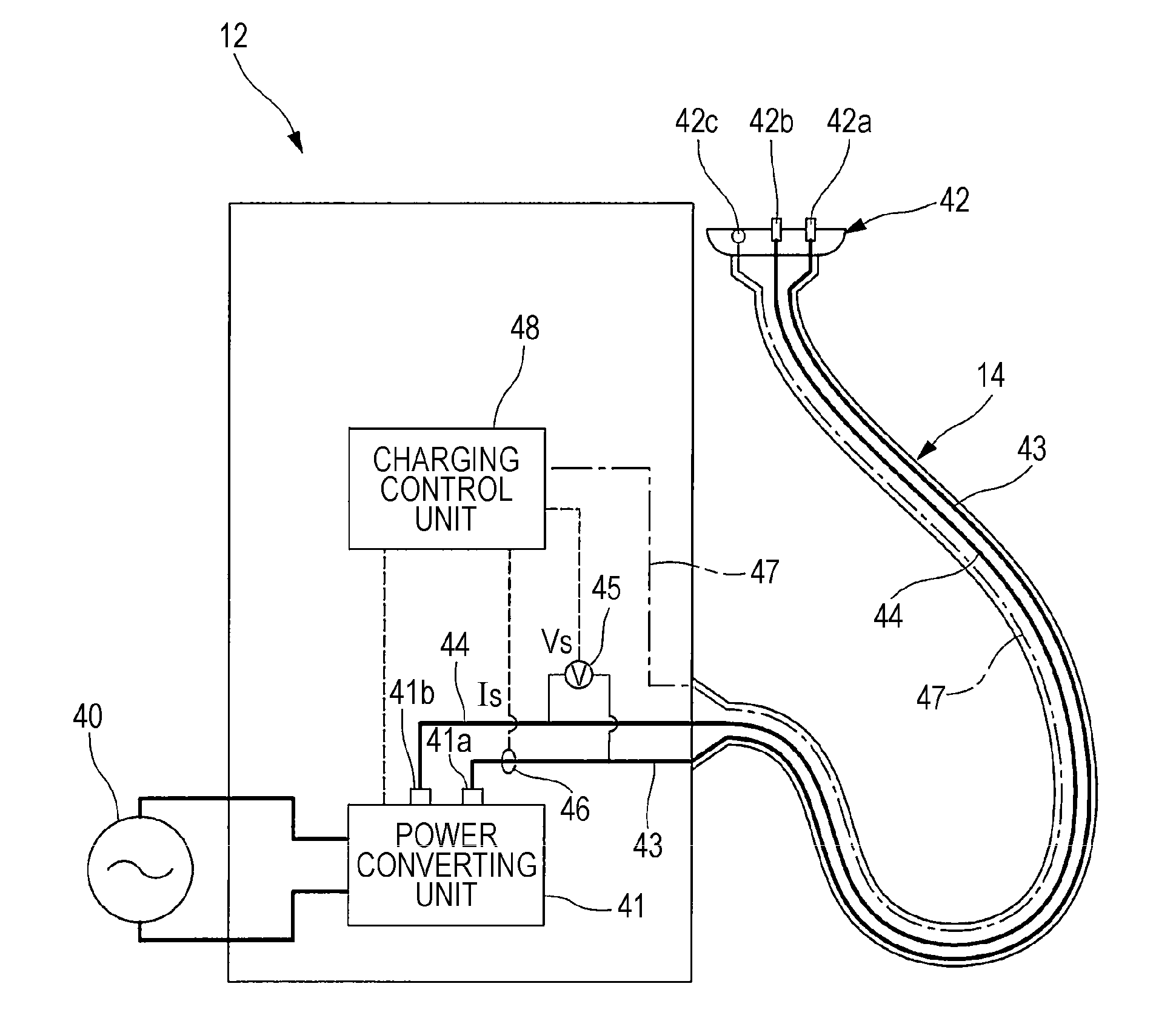
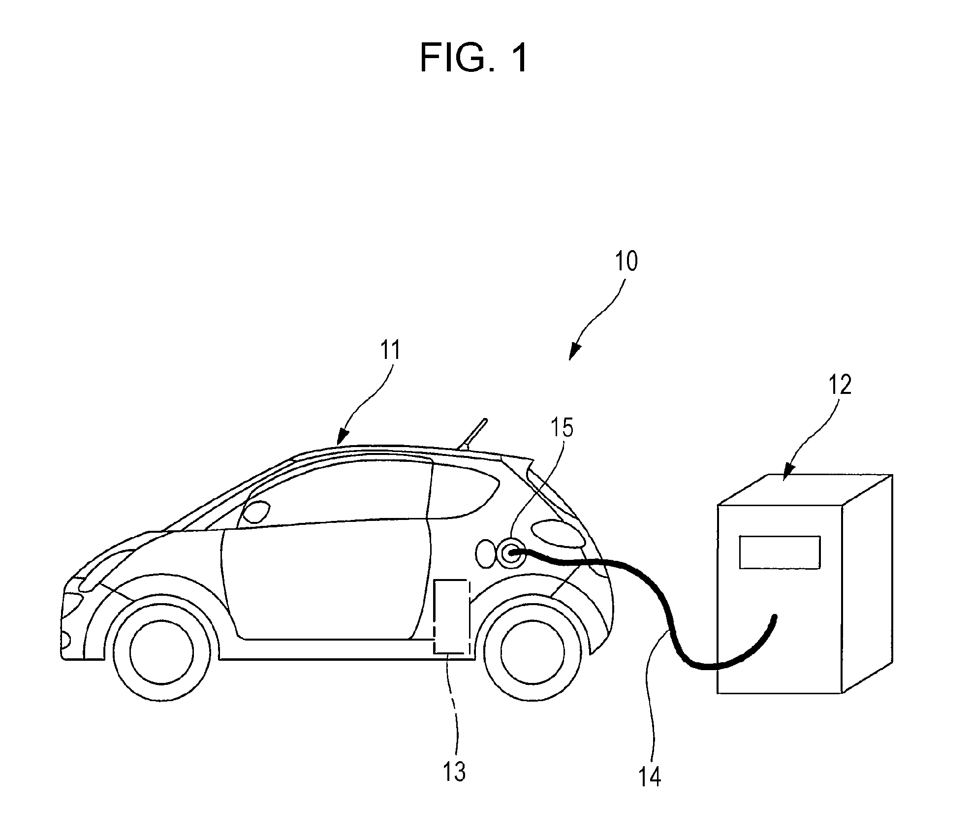
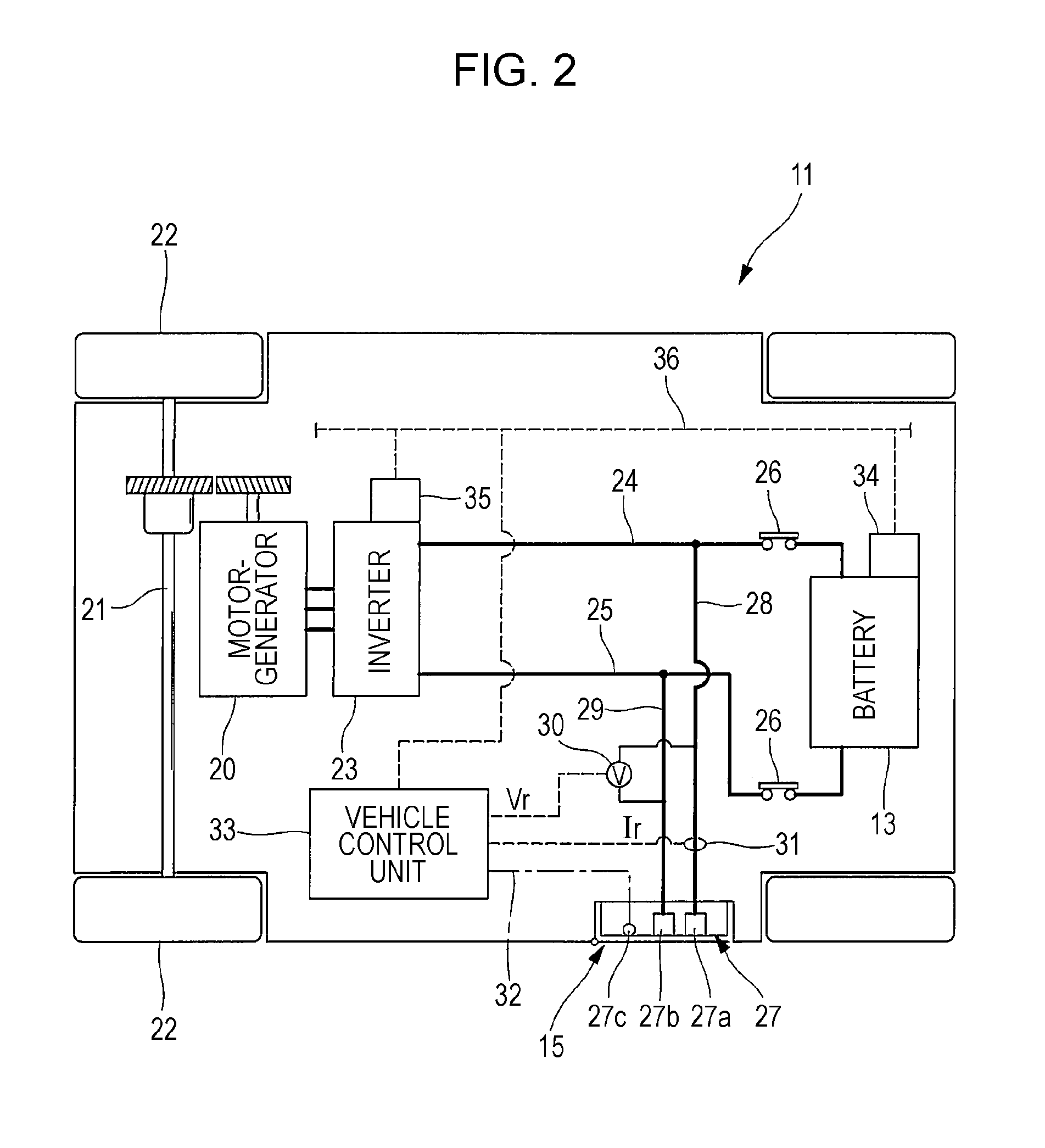
[0024]An embodiment of the present invention will hereunder be described with reference to the drawings. FIG. 1 is a schematic diagram showing a case in which charging is preformed with an electric charging system 10 according to an embodiment of the present invention. FIG. 2 is a schematic diagram showing an internal structure of an electric vehicle 11 constituting the electric charging system 10. FIG. 3 is a schematic diagram showing an internal structure of an electric charger 12 constituting the electric charging system 10. As shown in FIG. 1 the electric vehicle 11 is provided with a battery 13 as an electric storage device. When the battery 13 is charged, a charging cable 14 of the electric charger 12 is connected to a charging port 13 of the electric vehicle 11. The electric charger 12 charges the battery 13 to a predetermined state-of-charge (SOC), controlling a charging current and a charging voltage to be supplied to the electric vehicle 11.

[0025]As shown in FIG. 2, the el...


PUM


Abstract

In an electric charging system, a charging cable of an electric charger is connected to an electric vehicle, and a supply voltage at the electric charger is temporarily raised and dropped. A receiving voltage at the electric vehicle rises and falls in conjunction with to the supply voltage. Accordingly, a feature point is assigned to each of electric charger data obtained by applying a filtering process to the supply voltage and vehicle data obtained by applying a filtering process to the receiving voltage. Then a time lag between the electric charger data and the vehicle data due to filtering processing is calculated based on the feature points. Upon determining an insulation failure and the like between the electric charger and the electric vehicle, the electric charger data and the vehicle data are synchronized based on the time lag and then compared.

Description

CROSS REFERENCES TO RELATED APPLICATIONS[0001]The present application claims priority from Japanese Patent Application No. 2011-078294 filed on Mar. 31, 2011, the entire contents of which are hereby incorporated by reference.BACKGROUND OF THE INVENTION[0002]1. Field of the Invention[0003]The present invention relates to an electric charging system that connects an electric charger and an electric vehicle via a charging cable and charges an electric storage device mounted on the electric vehicle.[0004]2. Description of the Related Art[0005]In recent years, electric vehicles that are equipped with an electric motor for propulsion have been under development. The electric vehicle is equipped with an electric storage device such as battery. Upon charging the electric storage device, a charging cable extending from an electric charger is connected to a charging port of the electric vehicle (see, for example, Japanese Unexamined Patent Application Publication No. 2009-83670). Furthermore,...

Claims


Application Information

Patent Timeline
04 Oct 2012
Publication
US20120249069A1
IPC
H02J7/00
CPC
B60L1/08; Y02T10/70; B60L11/1803; B60L11/1816; B60L11/1846; B60L2210/30; B60L2210/40; B60L2230/12
Inventors
OHTOMO, YOSUKE