Stress measurement device and stress measurement method

a stress measurement and stress measurement technology, applied in the direction of measurement devices, force measurement, instruments, etc., can solve the problems of large reduction in the accuracy of image recording by the inability of the two-dimensional ccd camera to accurately record the scattered light, and the measurement time and manpower required for measurement. achieve the effect of high accuracy

Inactive Publication Date: 2012-10-04
NAT UNIV KYOTO INST OF TECH
View PDF6 Cites 14 Cited by
  • Summary
  • Abstract
  • Description
  • Claims
  • Application Information

AI Technical Summary

Benefits of technology

[0030]As described earlier, a stress measurement device in accordance with the present invention in which image processing is carried out with respect to each of a plurality of particles dispersed in a light-transmissive member to which light is emitted, movement directions and movement amounts of the respective plurality of particles in the light-transmissive member are found, and a three-dimensional stress occurring in the light-transmissive member is measured by use of a result of the finding, the stress measurement device includes: a retaining section which retains the light-transmissive member while soaking the light-transmissive member in a refractive index matching solution having a refractive index that matches a refractive index of the light-transmissive member; and a load application mechanism which applies a load to the light-transmissive member retained by the retaining section.
[0031]As described earlier, a stress measurement method in accordance with the present invention in which image processing is carried out with respect to each of a plurality of particles dispersed in a light-transmissive member to which light is emitted, movement directions and movement amounts of the respective plurality of particles in the light-transmissive member are found, and a three-dimensional stress occurring in the light-transmissive member is measured by use of a result of the finding, the stress measurement method includes the steps of: (a) retaining the light-transmissive member while soaking the light-transmissive member in a refractive index matching solution having a refractive index that matches a refractive index of the light-transmissive member; and (b) measuring a change over time in three-dimensional stress occurring in the light-transmissive member, while applying a load to the light-transmissive member soaked in the refractive index matching solution.
[0032]This yields an effect of measuring a change over time in three-dimensional stress with high accuracy even in a case where an RP model having a complicated shape is used to measure a three-dimensional stress by use of rapid prototyping (RP).

Problems solved by technology

Namely, the above technique has a problem such that enormous time and manpower is required for measurement of a change over time in three-dimensional stress field in a product.
This problem serves as a critical defect in realization of higher-speed product development.
This causes a problem such that the two-dimensional CCD camera cannot accurately record an image of the scattered light.
This problem causes a large reduction in accuracy of the image recording by the two-dimensional CCD camera especially in a case where the object to be measured has a complicated shape.

Method used


Image

  • Stress measurement device and stress measurement method
  • Stress measurement device and stress measurement method
  • Stress measurement device and stress measurement method

Examples


first embodiment

[0047]An embodiment of the present invention is described below with reference to FIGS. 1 through 6.

[0048](Principle of Stress Measurement)

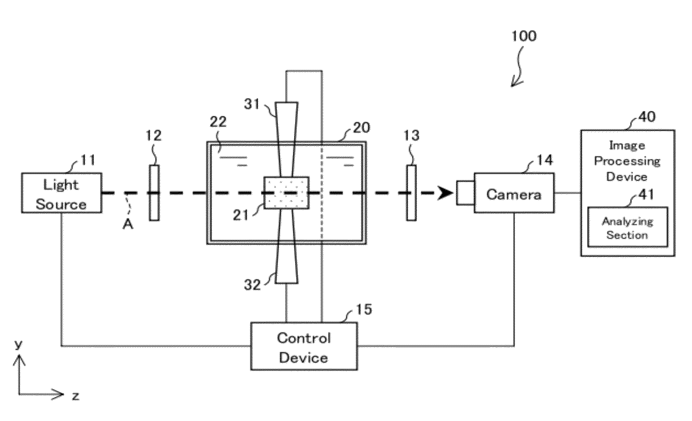
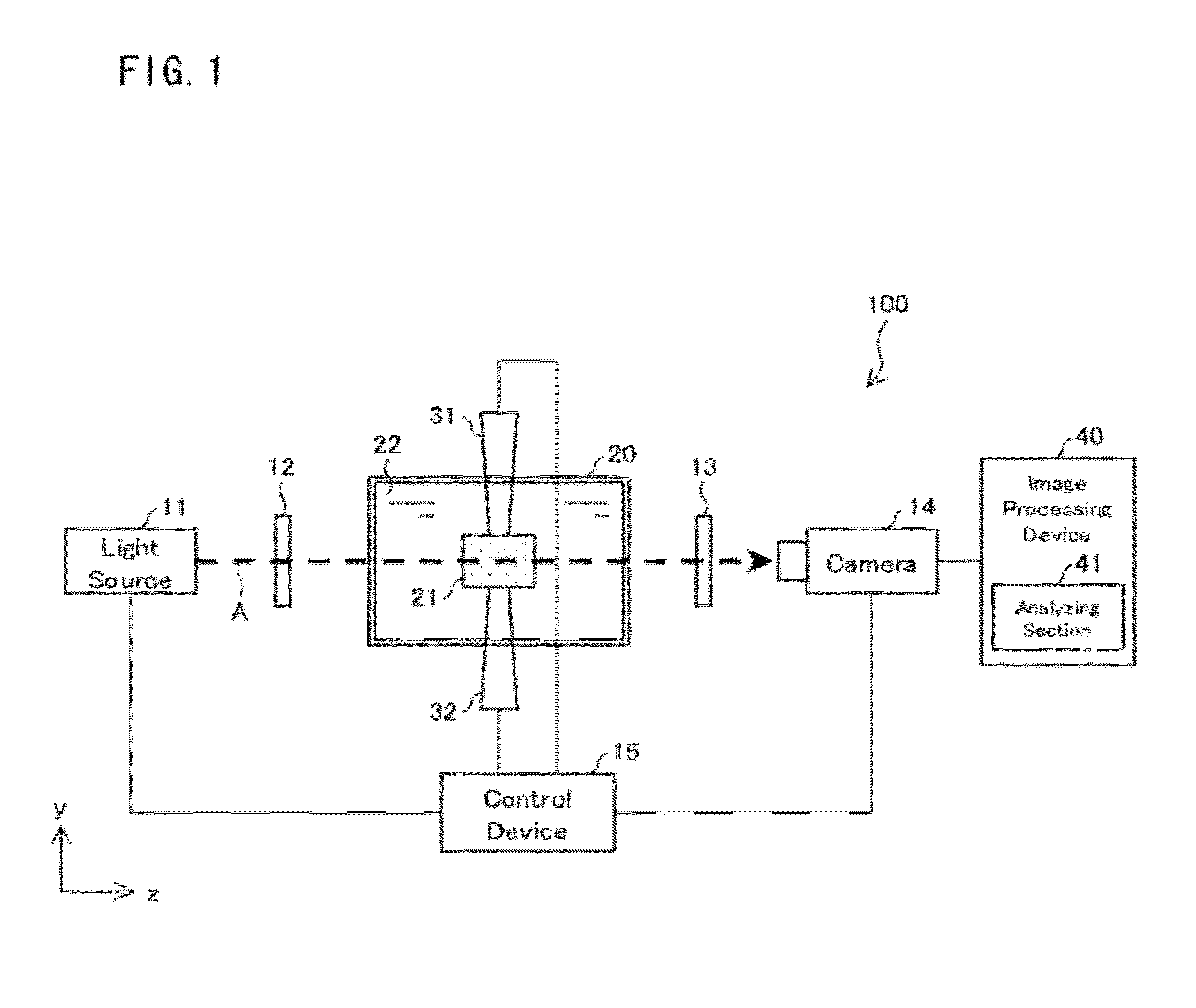
[0049]A stress measurement device in accordance with an embodiment of the present invention uses an RP model formed by three-dimensional CAD and an RP technique, so as to measure a stress field inside the RP model. In particular, the stress measurement device in accordance with the embodiment of the present invention is capable of measuring a change over time in stress field occurring inside the RP model while applying a load to the RP model.

[0050]Note that the three-dimensional CAD is general-purpose CAD which forms a three-dimensional model of a target object. The three-dimensional model formed by the three-dimensional CAD can faithfully reproduce a contour of the target object as a solid model. Any technique that is well known in this industry is applicable to such CAD regardless of a name thereof.

[0051]The RP technique is a technique for rapi...

second embodiment

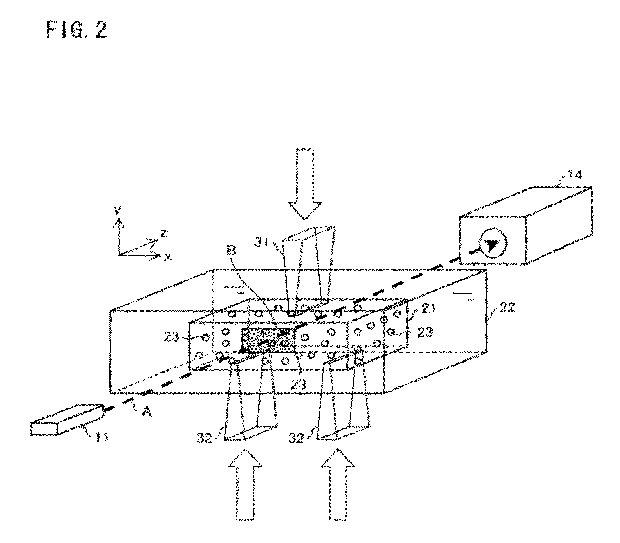
[0132]Next, the following description discusses a second embodiment of the present invention. According to the First Embodiment, many tracer particles are dispersed in, for example, a structure such as an automobile body and various parts to be contained in the automobile body, and displacements, i.e., movement directions and movement amounts of the respective many tracer particles are traced, so that a three-dimensional stress in the structure is measured. Note that the structure is an object formed by combining various members so that the object can resist a load such as an external force.

[0133]In contrast, the Second Embodiment of the present invention is an embodiment such that a change over time in three-dimensional stress in the structure and a change over time in three-dimensional velocity of a fluid are measured concurrently in a three-dimensional space in which the structure and the fluid exist concurrently.

[0134]Specifically, as in the case of the First Embodiment, accordi...


PUM


Abstract

A stress measurement device is arranged such that image processing is carried out with respect to each of a plurality of particles dispersed in an RP model to which light is emitted, movement directions and movement amounts of the respective plurality of particles in the RP model are found, and a three-dimensional stress occurring in the RP model is measured by use of a result of the finding. The stress measurement device includes: a retaining section which retains the RP model while soaking the RP model in a refractive index matching solution having a refractive index that matches a refractive index of the RP model; and a load application mechanism and a load application mechanism which apply a load to the RP model retained by the retaining section.

Description

TECHNICAL FIELD[0001]The present invention relates to a stress measurement device and a stress measurement method for measuring a three-dimensional stress in a product, particularly to a stress measurement device and a stress measurement method each of which uses rapid prototyping.BACKGROUND ART[0002]Conventional product design verification is exemplified by design verification using three-dimensional CAD and rapid prototyping (hereinafter may be abbreviated as “RP”). Note here that “three-dimensional CAD” refers to a tool for building a three-dimensional model by inputting three-dimensional coordinates. “RP” refers to a technique for rapidly forming a prototype of a product having a design shape.[0003]Commonly, in designing parts to be provided in a body of an automobile or the like, it is necessary to preliminarily verify, at a design stage, not only whether or not the parts can be contained in the body but also an analysis of strain on the body and each of the parts in a collisio...

Claims


Application Information

Patent Timeline
Patent Type & Authority Applications(United States)
IPC IPC(8): G01B11/16
CPCG01L1/247G03H2001/0033G03H1/0443
Inventor TANAKA, YOHSUKE
Owner NAT UNIV KYOTO INST OF TECH
Why Eureka
Try Eureka