System and Method for Transmission and Reception of Control Channels

a control channel and transmission system technology, applied in the field of digital communications, can solve the problems of reducing the overhead of communication between users, affecting the deployment of cellular systems, and affecting the reliability of communication channels, so as to achieve the effect of reducing the overhead of communication

Active Publication Date: 2012-10-04
FUTUREWEI TECH INC
View PDF3 Cites 96 Cited by
  • Summary
  • Abstract
  • Description
  • Claims
  • Application Information

AI Technical Summary

Benefits of technology

[0014]One advantage of an embodiment is that the use of resource assignment parameters provides orthogonality to control channels, permitting a larger number of control channels to be transmitted. The use of resource assignment parameters also enables the use of advanced transmission techniques.
[0015]A further advantage of an embodiment is that the resource assignment parameters are selected according to a pseudo-random sequence, which provides an additional degree of randomness, as well as not requiring a significant amount of coordination between communicating devices. Hence, communications overhead is reduced.

Problems solved by technology

While such a deployment is optimal when the user density is uniform, in practice, it has serious shortcomings because the user density and traffic demand are rarely uniform.
HetNets present new challenges to the deployment of a cellular system.
In particular, the cellular layout may not be as regular as for a HomoNet since it is dependent on the hot spot locations.
The close proximity can create a high level of interference for both user equipment (UE) (also known as mobile station (MS), terminal, user, subscriber, wireless node, and the like) and BSs.
The interference can affect both the data channels and control channels.
While solutions exist to mitigate interference on the data channels, no such solution has been defined yet for the control channels.

Method used


Image

  • System and Method for Transmission and Reception of Control Channels
  • System and Method for Transmission and Reception of Control Channels
  • System and Method for Transmission and Reception of Control Channels

Examples


Embodiment Construction

[0032]The operating of the current example embodiments and the structure thereof are discussed in detail below. It should be appreciated, however, that the present disclosure provides many applicable inventive concepts that can be embodied in a wide variety of specific contexts. The specific embodiments discussed are merely illustrative of specific structures of the disclosure and ways to operate the disclosure, and do not limit the scope of the disclosure.

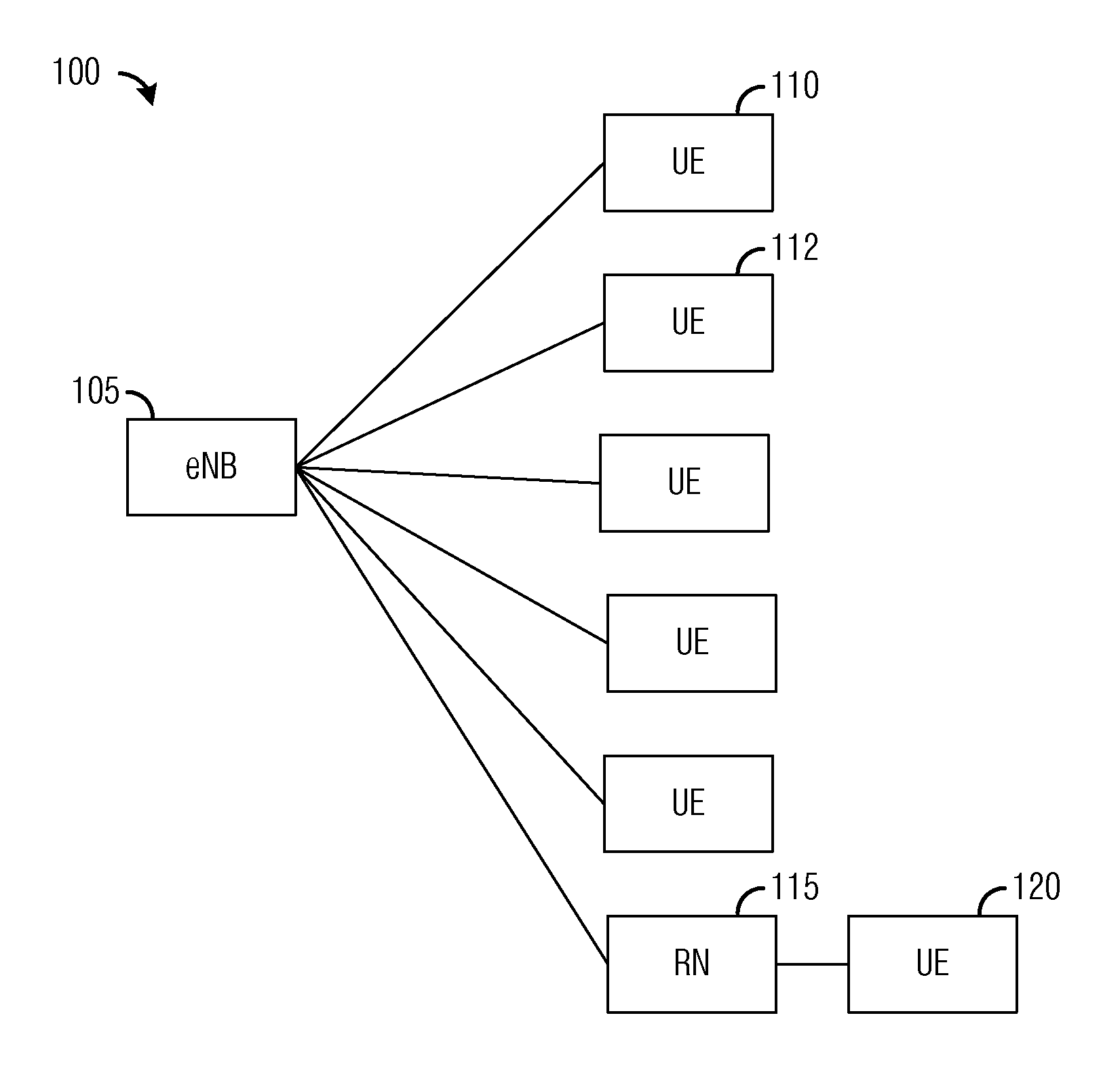
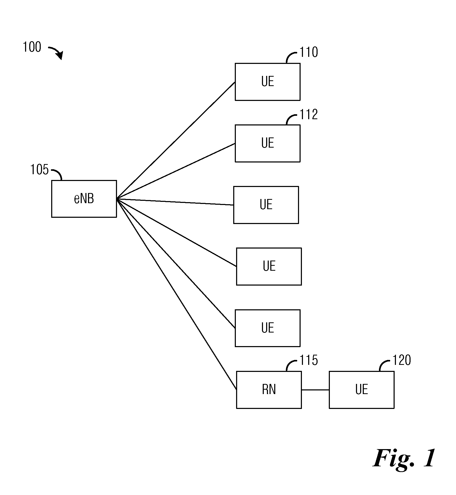
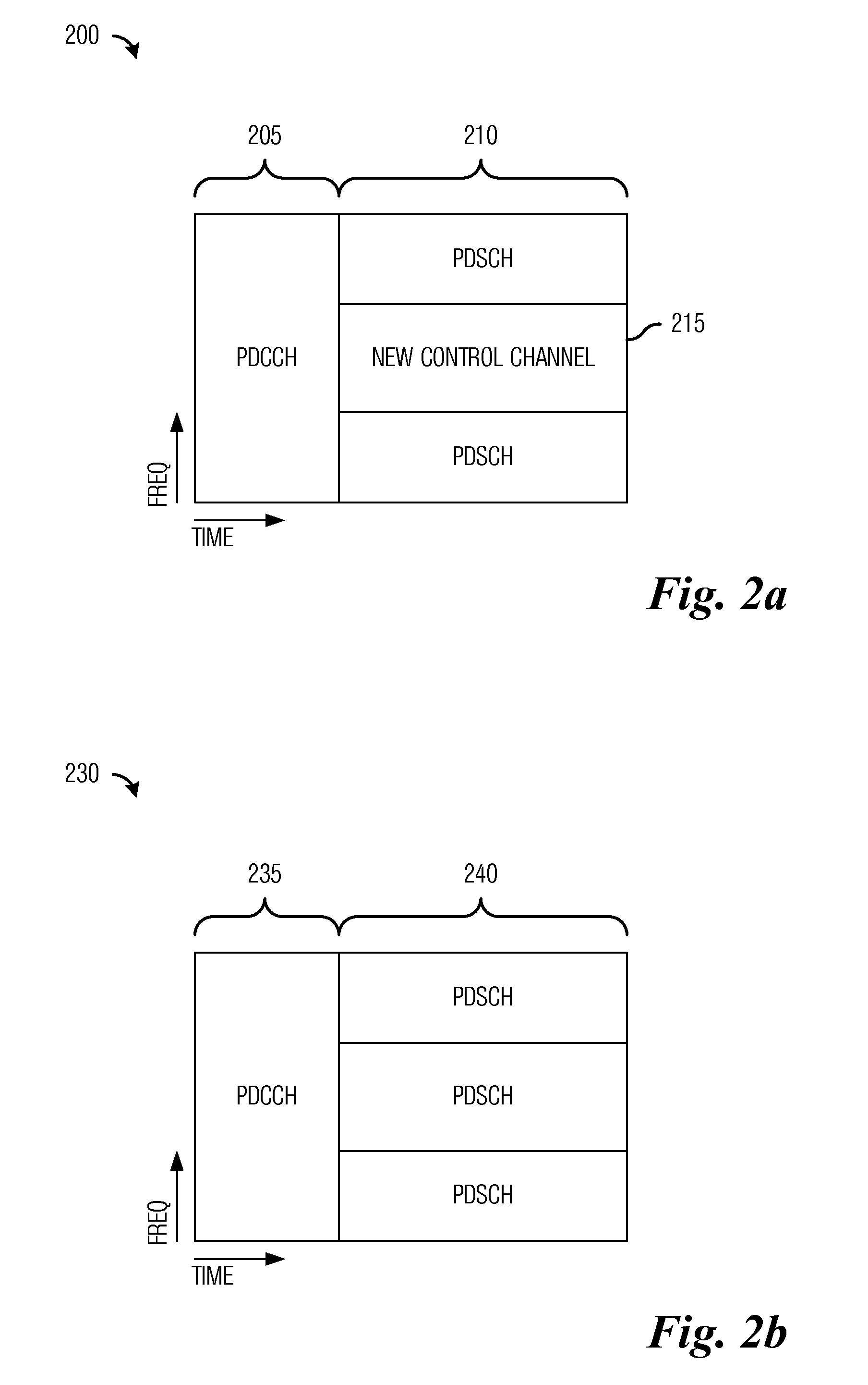
[0033]One embodiment of the disclosure relates to transmission and reception of control channels. For example, at an eNB, the eNB determines a resource assignment parameter according to a pseudo-random sequence that is derived from an identifier and then map a demodulation reference associated with the wireless node onto a first resource located in the data region of a subframe using the resource assignment parameter. The eNB also maps modulated control information associated with the wireless node onto a second resource in the da...


PUM


Abstract

A method for transmitting control information to a wireless node includes determining, by a communications controller, a first resource assignment parameter according to a pseudo-random sequence derived from an identifier, and mapping, by the communications controller, using the first resource assignment parameter, a demodulation reference signal associated with the wireless node onto a first resource located in a data region of a subframe. The method also includes mapping, by the communications controller, modulated control information associated with the wireless node onto a second resource located in the data region of the subframe, and transmitting, by the communications controller, the subframe to the wireless node.

Description

[0001]This application claims the benefit of U.S. Provisional Applications: No. 61 / 471,049, filed on Apr. 1, 2011, entitled “System and Method for Signaling a Location of a Control Channel,” No. 61 / 470,940, filed on Apr. 1, 2011, entitled “System and Method for Transmission and Reception of Control Channels in a Communications System,” No. 61 / 471,055, filed on Apr. 1, 2011, entitled “System and Method for Transmission and Reception of Control Channels,” and No. 61 / 471,061, filed on Apr. 1, 2011, entitled “System and Method for Transmission and Reception of Control Channels,” which applications are hereby incorporated herein by reference.CROSS-REFERENCE TO RELATED APPLICATIONS[0002]This application is related to the following co-assigned patent applications: Ser. No. 13 / 434,449, filed Mar. 29, 2012, Attorney Docket Number HW 83138110US05, entitled “System and Method for Transmission and Reception of Control Channels in a Communications System”; Ser. No. 13 / 436,375, filed March 30, 20...

Claims


Application Information

Patent Timeline
Patent Type & Authority Applications(United States)
IPC IPC(8): H04W72/04
CPCH04W48/12H04W24/10H04W72/23H04W72/20
Inventor QU, BINGYUSARTORI, PHILIPPEXIAO, WEIMINCLASSON, BRIANDESAI, VIPUL
Owner FUTUREWEI TECH INC
Why Eureka
Try Eureka