Method of directional resistivity logging

a directional resistivity and logging technology, applied in seismology for waterlogging, using reradiation, instruments, etc., can solve the problems of not being suitable for real-time drilling operations, not being able to generally be forward modeled, and requiring a highly processing intensive three-dimensional forward model, so as to reduce the processing time of inversion, and improve the accuracy of inversion

Inactive Publication Date: 2012-10-04
SCHLUMBERGER TECH CORP
View PDF2 Cites 15 Cited by
  • Summary
  • Abstract
  • Description
  • Claims
  • Application Information

AI Technical Summary

Benefits of technology

[0009]Exemplary embodiments of the present invention may advantageously provide several technical advantages. For example, the present invention advantageously provides a fast inversion methodology that may be utilized on board a conventional downhole processor. Exemplary embodiment of the invention may reduce inversion processing time by a factor of 50 or more. Moreover the method may be used to compute a sensitivity matrix (e.g., a Jacobin matrix) for post-processing inversion which may further decrease the inversion processing time.
[0010]Moreover, one exemplary embodiment of the pr

Problems solved by technology

Such a formation structure can not generally be forward modeled using prior art one-dimensional models and therefore tends to require a highly processing i

Method used


Image

  • Method of directional resistivity logging
  • Method of directional resistivity logging
  • Method of directional resistivity logging

Examples


embodiment 50

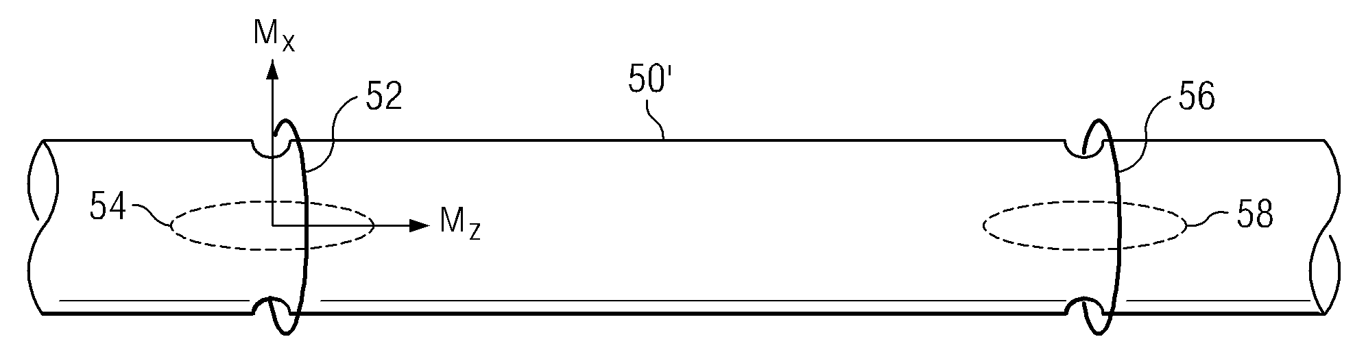
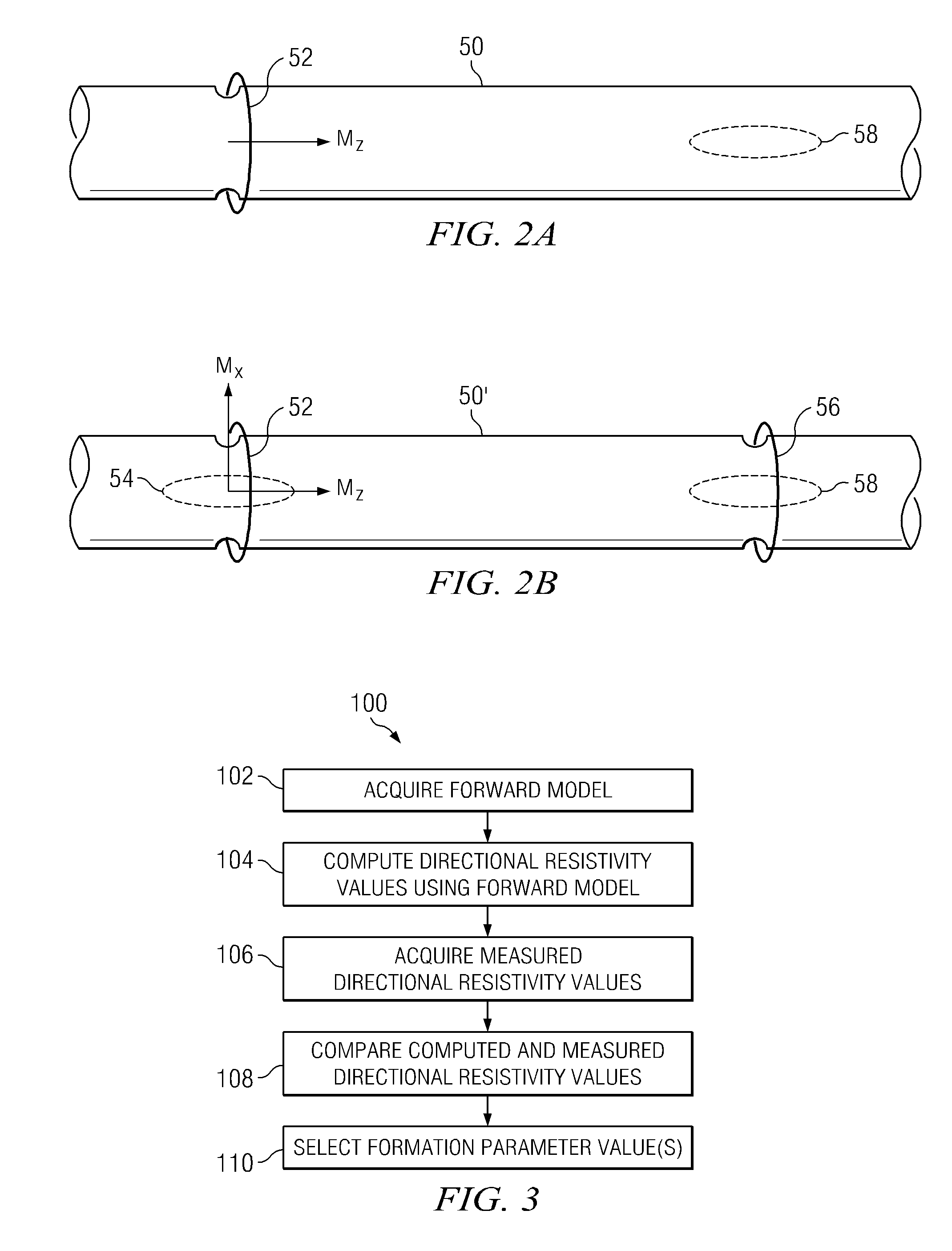
[0026]FIG. 2B depicts a tool embodiment 50′ including first and second collocated axial and transverse transmitting antennae 52 and 54 and first and second collocated axial and transverse receiving antennae 56 and 58. In the depicted reference frame, the axial and transverse antennae have magnetic moments MZ and MX that are coincident and transverse with the tool axis. Those of ordinary skill in the art will readily appreciate that logging tool 50′ is configured to measure the HZX and HXZ cross coupling components as well as the HZZ and HXX coupling components.

embodiment 100

[0027]FIG. 3 depicts a flow chart of one exemplary method embodiment 100 in accordance with the present invention. Method 100 includes a method for estimating a formation parameter from acquired directional resistivity measurements. The parameter may include, for example, at least one distance to a remote bed. A forward model of a subterranean formation is acquired at 102. The forward model includes at least one analytical expression relating a directional resistivity measurement (e.g., the aforementioned HZX and HXZ cross coupling components and / or the HXX and HZZ coupling component) to various formation parameters (e.g., distance to a remote bed). The analytical expression includes at least one image source term. Such image source terms are described in more detail below. At 104 a processor utilizes the analytical expression(s) to compute a plurality of hypothetical directional resistivity measurements at a corresponding plurality of formation parameter values. The processor is pr...


PUM


Abstract

A method for estimating at least one formation parameter from a directional resistivity measurement includes computing a plurality of hypothetical directional resistivity values at a corresponding plurality of formation parameter values. The computation makes use of a forward model having at least one analytical expression that relates a directional resistivity measurement to the formation parameter. The analytical expression includes at least one image source term. Comparison of computed directional resistivity values with measured direct resistivity values enables a value of at least one formation parameter to be selected. The method may be implemented on a downhole processor.

Description

RELATED APPLICATIONS[0001]None.FIELD OF THE INVENTION[0002]The present invention relates generally to methods for making subterranean directional resistivity measurements. More particularly, the present invention relates to an inversion methodology that makes use of an analytical expression including at least one image source term.BACKGROUND OF THE INVENTION[0003]The use of electrical measurements in prior art downhole applications, such as logging while drilling (LWD), measurement while drilling (MWD), and wireline logging applications is well known. Such techniques may be utilized to determine a subterranean formation resistivity, which, along with formation porosity measurements, is often used to indicate the presence of hydrocarbons in the formation. For example, it is known in the art that porous formations having a high electrical resistivity often contain hydrocarbons, such as crude oil, while porous formations having a low electrical resistivity are often water saturated. It...

Claims


Application Information

Patent Timeline
IPC IPC(8): G06F19/00
CPCG01V3/38
Inventor DONG, QIUZHAOWANG, TSILI
Owner SCHLUMBERGER TECH CORP
Why Eureka
Try Eureka