Heating system

Active Publication Date: 2012-10-11
DENG DAVID
View PDF5 Cites 16 Cited by
  • Summary
  • Abstract
  • Description
  • Claims
  • Application Information

AI Technical Summary

Benefits of technology

[0024]According to certain embodiments, the pressure of the flow can act on the biasing member through contact with the movable body. In the second position of some embodiments, the movable body can be configured to sealingly connect to the outlet. The movable body may further comprise a channel passing therethrough. In addition, the burner nozzle

Problems solved by technology

However, such devices and certain components the

Method used


Image

  • Heating system
  • Heating system
  • Heating system

Examples


Example

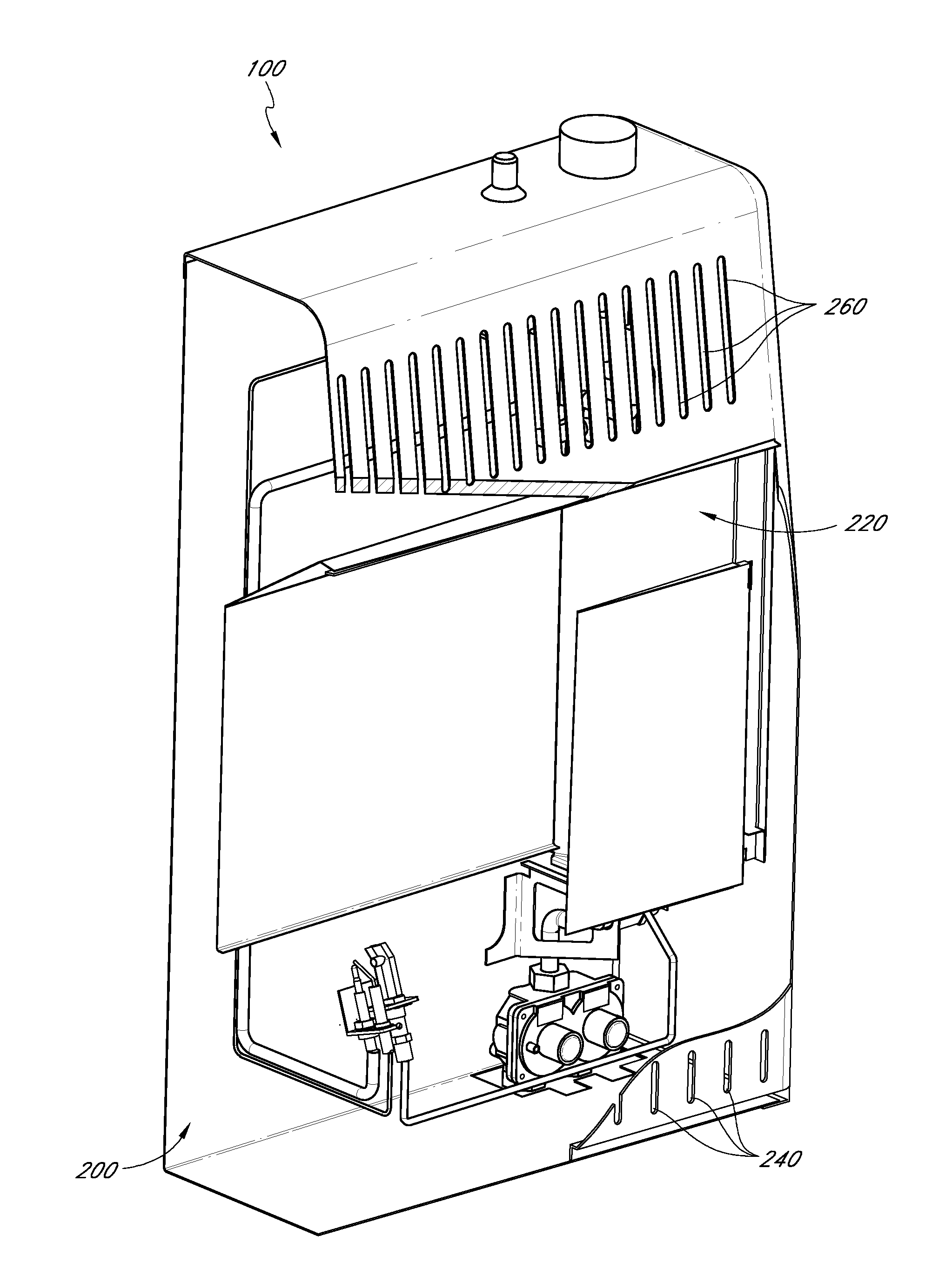
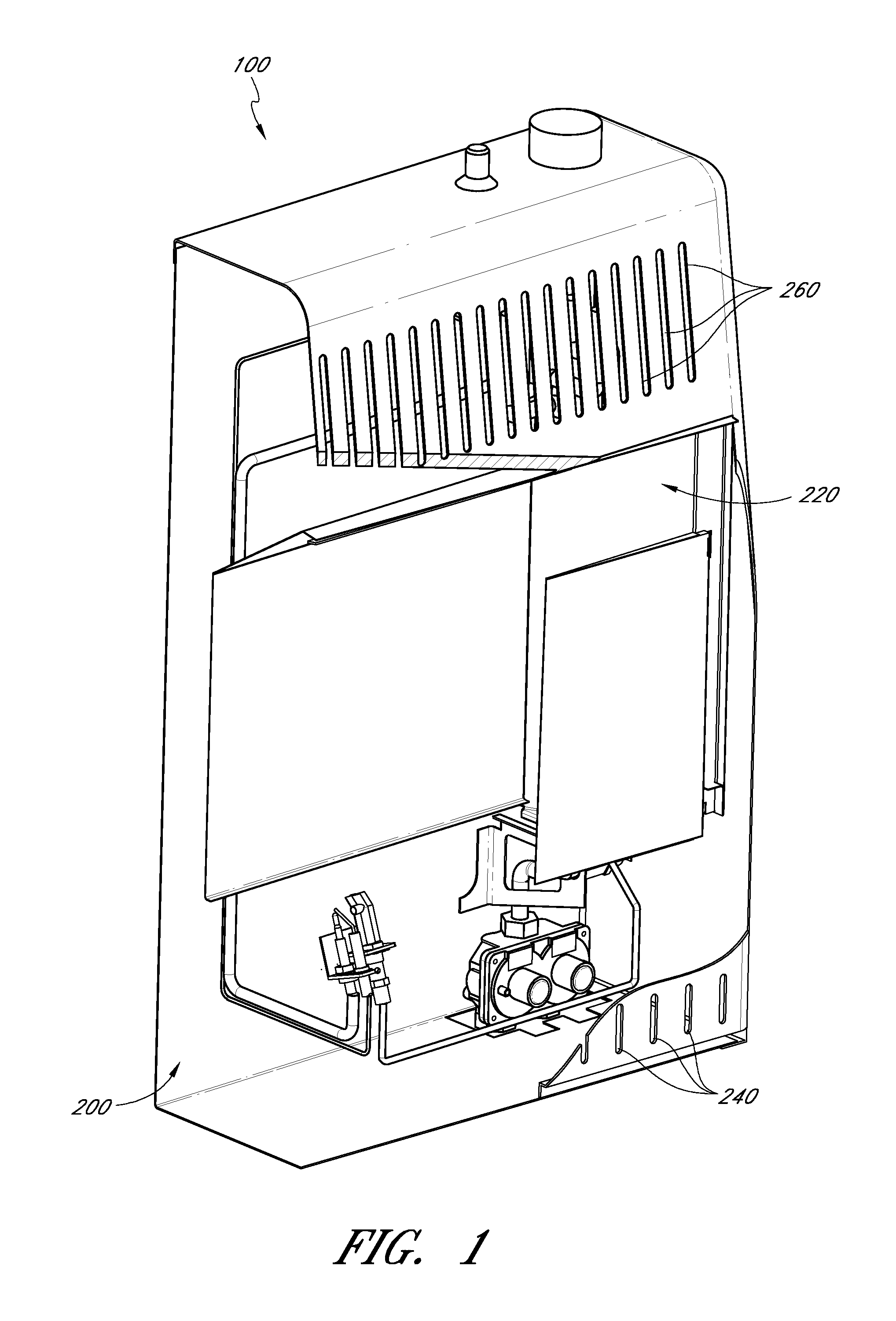
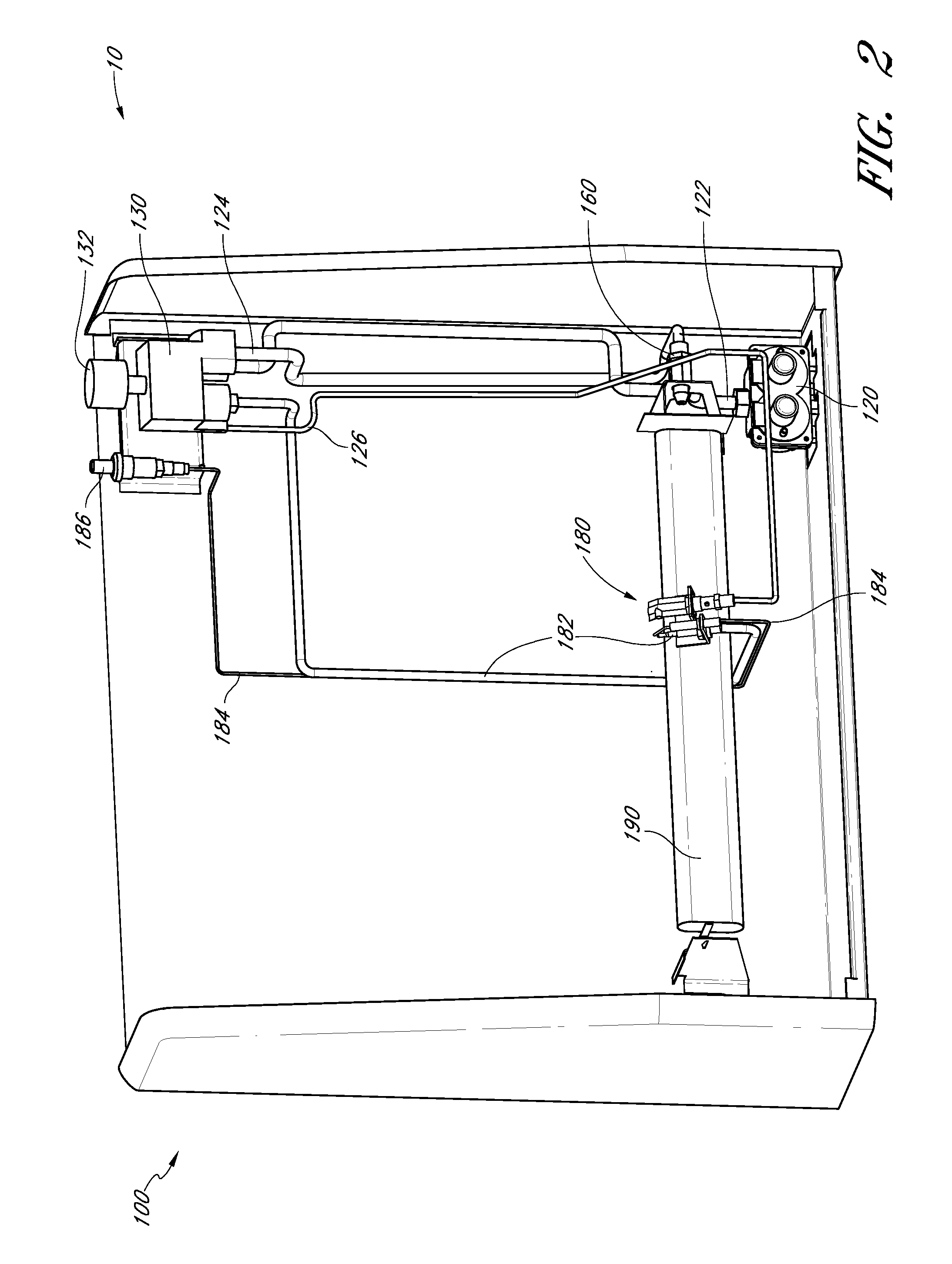
[0087]Many varieties of space heaters, wall heaters, stoves, fireplaces, fireplace inserts, gas logs, and other heat-producing devices employ combustible fluid fuels, such as liquid propane and natural gas. The term “fluid,” as used herein, is a broad term used in its ordinary sense, and includes materials or substances capable of fluid flow, such as, for example, one or more gases, one or more liquids, or any combination thereof. Fluid-fueled units, such as those listed above, generally are designed to operate with a single fluid fuel type at a specific pressure or within a range of pressures. For example, some fluid-fueled heaters that are configured to be installed on a wall or a floor operate with natural gas at a pressure in a range from about 3 inches of water column to about 6 inches of water column, while others are configured to operate with liquid propane at a pressure in a range from about 8 inches of water column to about 12 inches of water column. Similarly, some gas fi...


PUM


Abstract

A heating system can include certain pressure sensitive features. These features can be configured to change from a first position to a second position based on a pressure of a fuel flowing into the feature. These features can include, fuel selector valves, pressure regulators, burner nozzles, and oxygen depletion sensor nozzles, among other features.

Description

CROSS-REFERENCE TO RELATED APPLICATIONS[0001]This application claims priority to U.S. Provisional Application No. 61 / 473,714 (PROCUSA.070PR4), filed Apr. 8, 2011, and Chinese Patent Application No. 201120401676.3, filed on Oct. 20, 2011. The entire contents of all of the applications to which this application claims priority are hereby incorporated by reference and made a part of this specification.BACKGROUND OF THE INVENTION[0002]1. Field of the Invention[0003]Certain embodiments disclosed herein relate generally to a heating source for use in a gas appliance. Aspects of certain embodiments may be particularly adapted for single fuel, dual fuel or multi-fuel use. The gas appliance can include, but is not limited to: heaters, boilers, dryers, washing machines, ovens, fireplaces, stoves, etc.[0004]2. Description of the Related Art[0005]Many varieties of heating sources, such as heaters, boilers, dryers, washing machines, ovens, fireplaces, stoves, and other heat-producing devices uti...

Claims


Application Information

Patent Timeline
IPC IPC(8): F24C3/00F16K31/44
CPCF23N1/007F23N5/006F23D14/48F23D14/64F23N2035/26F16K21/02F16K11/105F16K17/06F16K17/34F16K17/36F23N2037/08F23N2235/26F23N2237/08Y10T137/2668Y10T137/2688Y10T137/2693
Inventor DENG, DAVID
Owner DENG DAVID
Why Eureka
Try Eureka