Controlled, diffused, and augmented wind energy generation apparatus and system

a technology of wind energy generation apparatus and system, which is applied in the direction of electric generator control, machines/engines, liquid fuel engines, etc., can solve the problems of ineffectiveness, repetitiveness and cost, and inability to integrate, so as to maximize the performance of the present disclosure, reduce weight, and reduce pore size

Inactive Publication Date: 2012-10-11
AWR ENERGY
View PDF0 Cites 11 Cited by
  • Summary
  • Abstract
  • Description
  • Claims
  • Application Information

AI Technical Summary

Benefits of technology

[0077]Yet another exemplary material may be the use of skeletal frames with flexible membranes that enable a flexible shroud. By using a trellis-type shroud that is comprised primarily of nano pieces, carbon fiber meshes with Dacron surfaces, or flexible silicone/natural rubbers, the present disclosure enables not just a stiffened shroud, but also whole surface flexibility. Additionally, the use of a porous shroud allows wind to flow through at a very small pore scale. Porosity changes along the entire diffuser may be controlled and changed to maximize performance of the present disclosure.
[0078]Yet another exemplary material may be the use of sound dampening or absorbing composites to control or eliminate emitted noises from the diffuser through the use of select material types, architecture, processes, assembly, and installation. Both material choices and physical shape can be designed and tailo

Problems solved by technology

Many have tried to become independent from the public power grid, but to accomplish this, one has to create a multi level power platform that has the flexibility of using many natural resources, since some like the wind are not consistent and are unreliable.
The conventional solution requires multiple controllers, allows no integration, is not effective, and is repetitive and

Method used


Image

  • Controlled, diffused, and augmented wind energy generation apparatus and system
  • Controlled, diffused, and augmented wind energy generation apparatus and system
  • Controlled, diffused, and augmented wind energy generation apparatus and system

Examples


Embodiment Construction

[0044]Although described with particular reference to wind energy generation, those with skill in the arts will recognize that the disclosed embodiments have relevance to a wide variety of areas in addition to those specific examples described below.

[0045]All references, including publications, patent applications, and patents, cited herein are hereby incorporated by reference to the same extent as if each reference were individually and specifically indicated to be incorporated by reference and were set forth in its entirety herein.

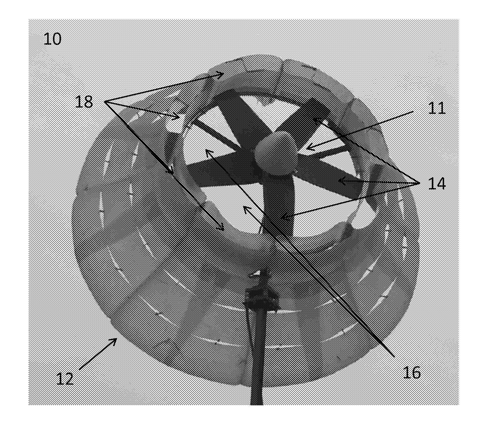
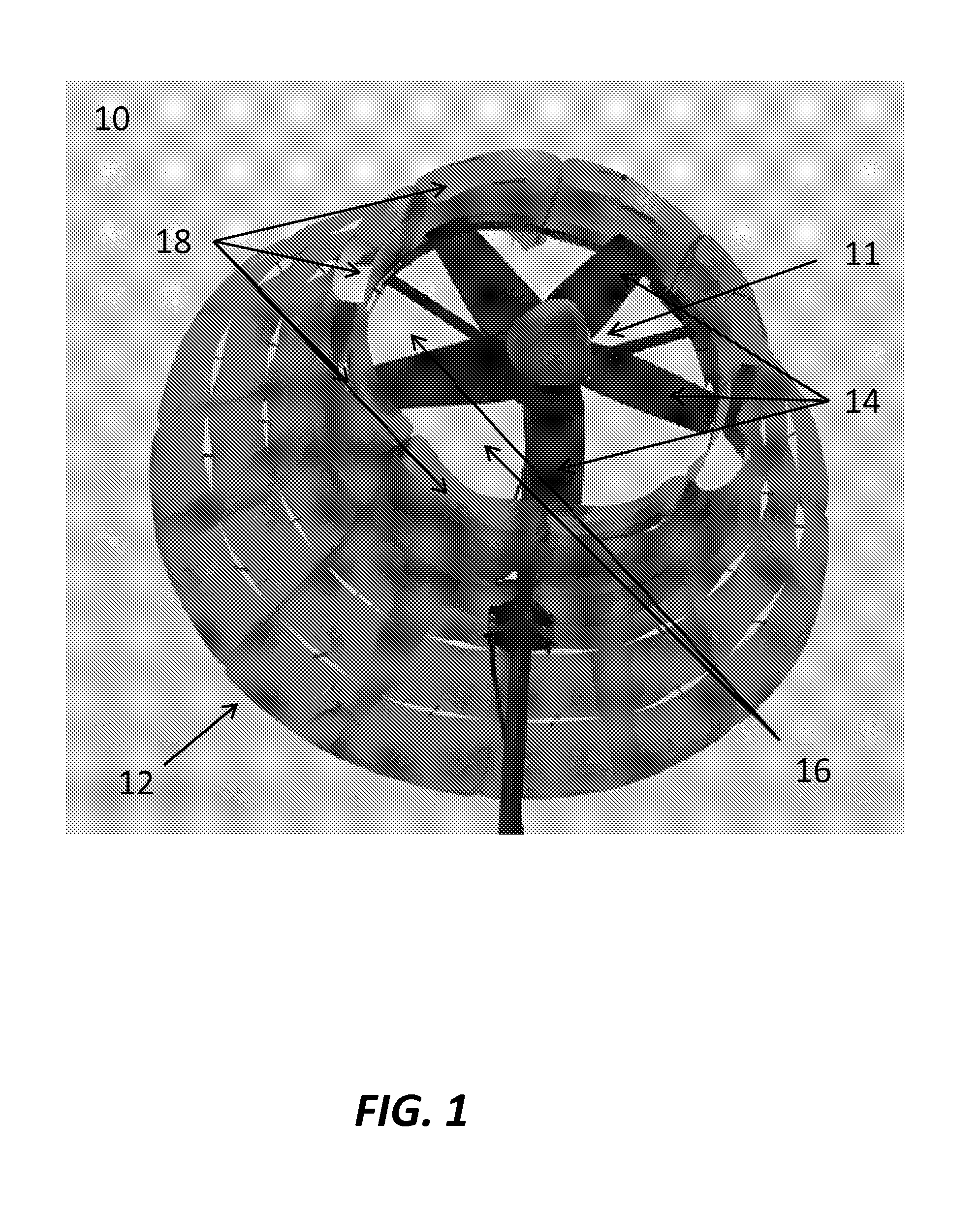
[0046]FIG. 1 shows an exemplary diffuser augmented wind energy generation system 10. A mass flow gap subsequently mixes with the main flow in the center section of the exemplary diffuser augmented wind energy generation system 10. Diffuser 12 contains a large diameter inlet 16 and a mass flow gap, herein called bypass 18. Further, inlet 16 may contain a generator 11. Subcomponents of generator 11 may include a plurality of rotor blades 14, which are rota...


PUM


Abstract

An apparatus and system for increasing power output for wind energy generation through a diffusing mechanism. An apparatus and system for mixing the wake and external flow, thereby permitting increasing mass-flux for wind energy generation. An apparatus to control and energize the boundary layer associated with wind energy generation by the use of an intake, bypass, and diffuser mechanism. A distributed load support provided by a wind energy generation apparatus and system. An apparatus for augmenting a wind energy generation system by achieving an increased energy extraction per unit of primary mass-flow.

Description

CROSS-REFERENCE TO RELATED APPLICATION[0001]The present application claims priority to U.S. Provisional Application Ser. No. 61 / 290,396, filed on Dec. 28, 2009, which is hereby incorporated by reference in its entirety.FIELD[0002]This disclosure relates in general to the field of energy production and more particularly to wind turbines.BACKGROUND OF THE INVENTION[0003]Substantial literature exists, describing the use of wind turbines to transfer the kinetic energy of the wind into electrical energy via an electrical generator. The aerodynamics of a wind turbine system influence performance and the cost of energy.[0004]Most conventional wind energy generation systems may be of three and two bladed systems with airfoils rotating freely and un-shrouded. Some shrouded systems may have been designed to reduce blade tip losses and improve aerodynamic efficiency by use of a shroud surrounding the aerodynamic swept area. Additionally, wind energy generation systems employing diffuser augmen...

Claims


Application Information

Patent Timeline
IPC IPC(8): F03D9/00F03D11/00
CPCY02E10/72F03D1/04
Inventor MARIN, ED
Owner AWR ENERGY
Why Eureka
Try Eureka