Harmonic mitigation devices and applications thereof

a technology of harmonic distortion and mitigation device, which is applied in the direction of harmonic reduction arrangement, inductance, power conversion system, etc., can solve the problems that variable frequency drives can experience substantial harmonic distortion caused, and achieve the effect of effective magnetic, high permeability, and sufficient heating

Active Publication Date: 2012-10-11
MTE CORP
View PDF2 Cites 14 Cited by
  • Summary
  • Abstract
  • Description
  • Claims
  • Application Information

AI Technical Summary

Benefits of technology

[0004]In some embodiments, the instant invention can provide an inductor that at least includes the following component(s): at least one FAP positioned along at least one magnetic flux path; where the at least one FAP is a high permeability core gap piec

Problems solved by technology

Typically, variable frequency drives can experience sub

Method used


Image

  • Harmonic mitigation devices and applications thereof
  • Harmonic mitigation devices and applications thereof
  • Harmonic mitigation devices and applications thereof

Examples


example 1

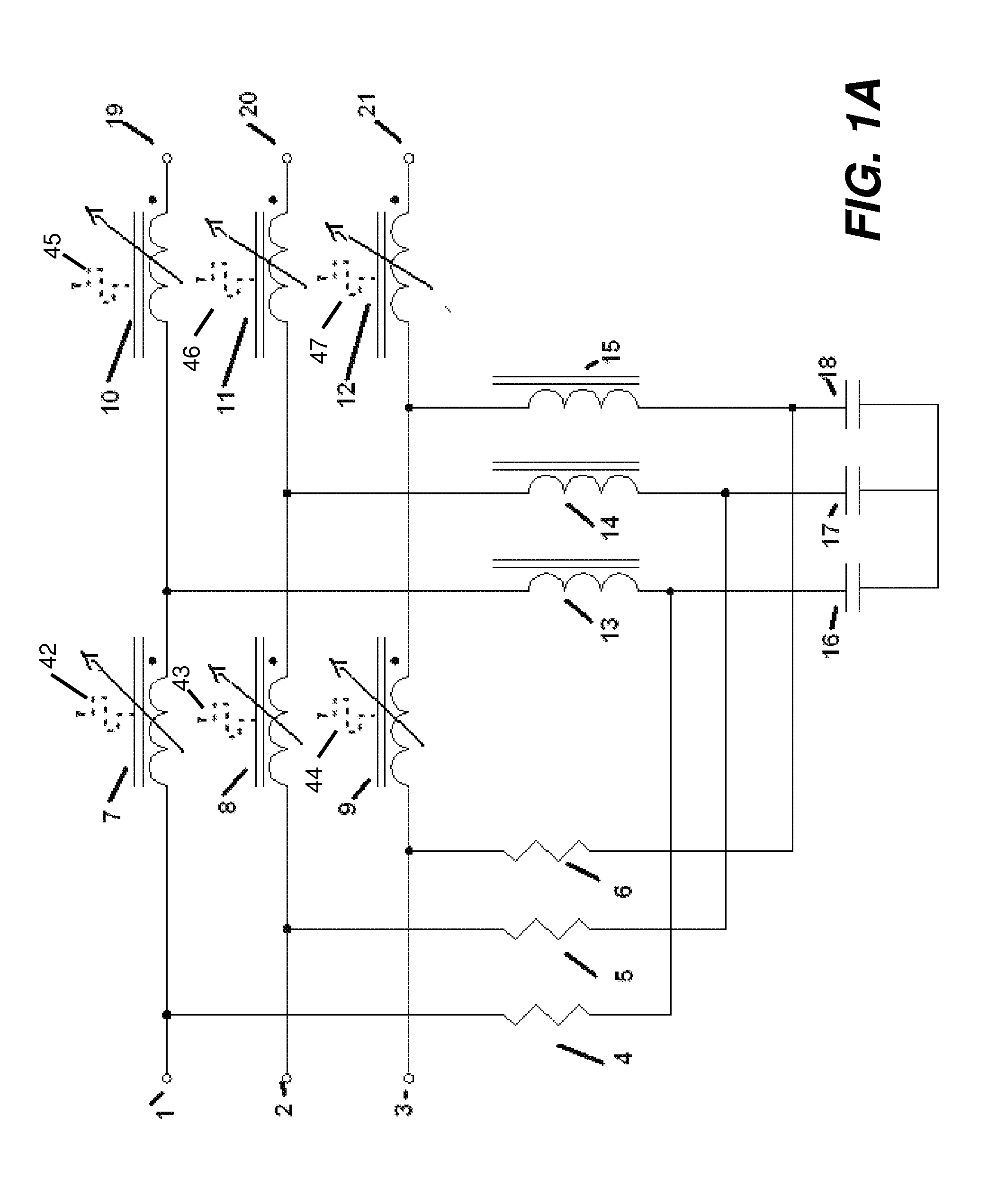
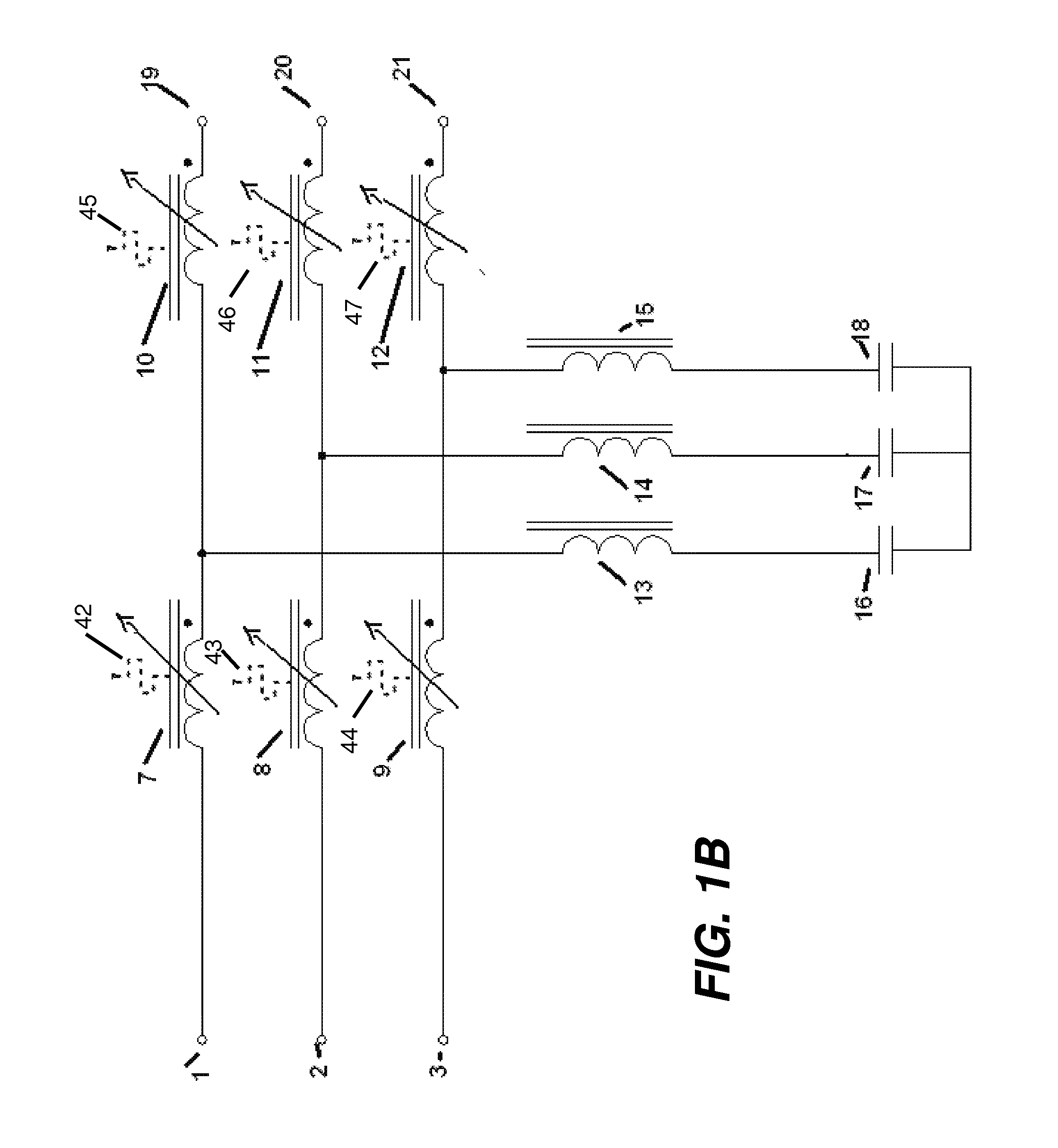
Adaptive Passive Three Phase Filter

[0107]In some embodiments, passive harmonic filters connect in series at the input to any six pulse drive. In some embodiments, being low pass filters, the passive harmonic filters attenuates each harmonic frequency, resulting in the lower harmonic distortion levels. In some embodiments, the passive harmonic filters allow for operating conditions such as unbalanced line voltages and from no load to full load. In some embodiments, the passive harmonic filters can result in provide losses that are less than one percent of the load power rating. In some embodiments, the passive harmonic filters do not cause power system resonance problems and do not attract harmonics from other non-linear loads sharing the same power source. In some embodiments, the passive harmonic filters can be utilized for variable frequency, variable torque applications.

[0108]In some embodiments, the passive harmonic filters of the instant invention can convert any six pulse driv...

example 2

Adaptive Passive Single Phase Filter

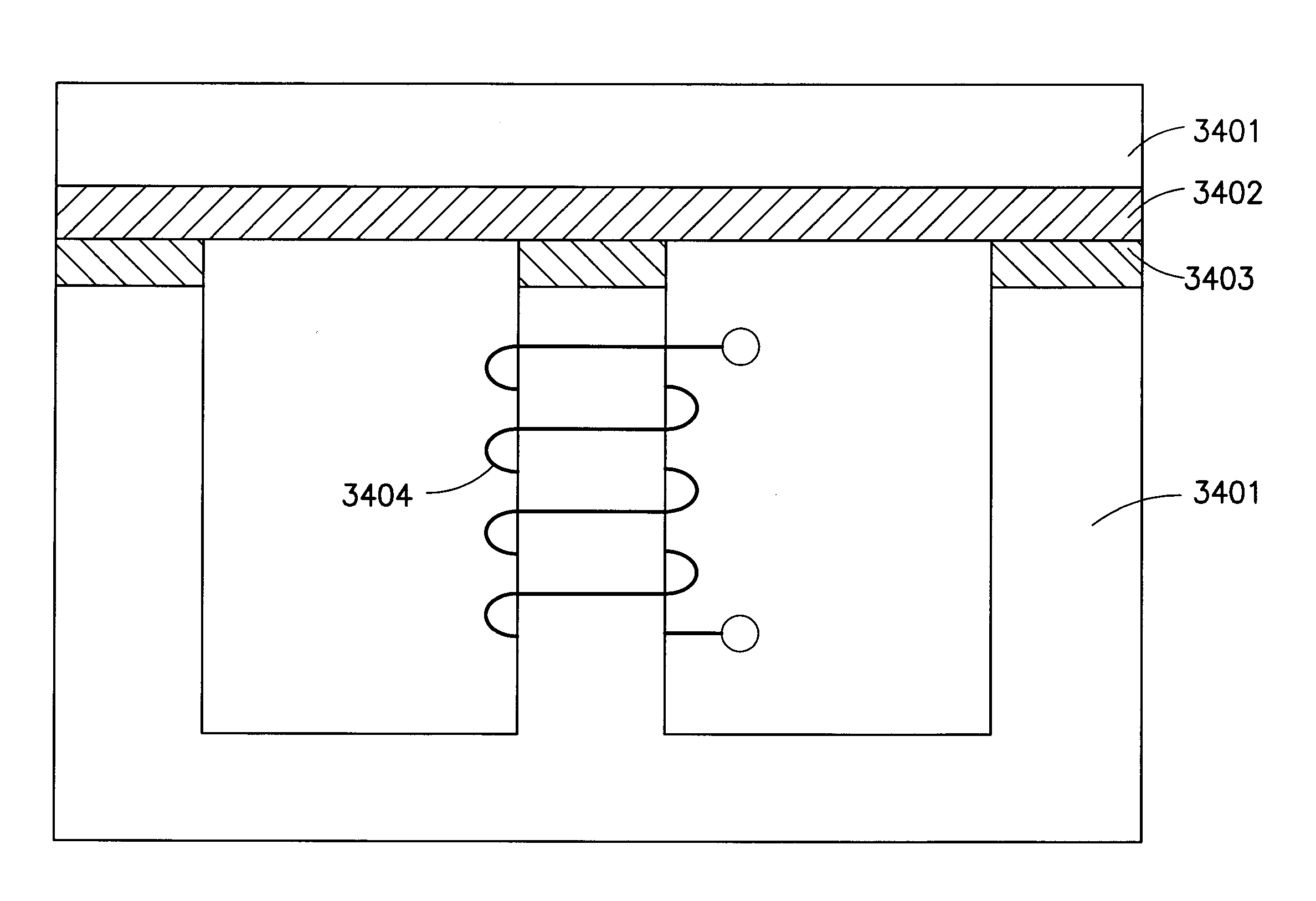
[0112]In some embodiments, the adaptive passive single phase filters of the instant invention can be utilized on four pulse rectifier supplies. FIG. 19 shows a general topology of single phase filters. FIG. 20 shows a cross-section of the adaptive passive single phase inductor in accordance with some embodiments of the instant invention. FIG. 2 shows a cross-section of the adaptive passive inductor. While FIG. 20 shows an embodiment with an “EI” core construction, some embodiments of the instant invention can similarly be constructed with multiple gaps per a core leg. In some embodiments, the core can be constructed as having equal or unequal three legs. In FIG. 20, the “EI” core is identified as having three phase laminations 2001 and 2002. In FIG. 20, FAPs are marked as 2003, 2004, and 2005. In some embodiments, these FAPs may be of equal size and shape. In some embodiments, these FAPs be of different sizes and shapes. In some embodiments, thick...

example 3

Harmonic Filters with a Multi-Section Core

[0118]In some embodiments, as shown, for example, in FIGS. 2A-2B and 4A-4B, the instant invention can provide devices that at least include harmonic current filters having inductors with a common core that can be divided into at least two sections.


PUM


Abstract

In one embodiment, the instant invention can provide an inductor that at least includes the following component(s): at least one FAP positioned along at least one magnetic flux path; where the at least one FAP is a high permeability core gap piece; and where the at least one FAP has an effective magnetic permeability that varies based on at least in part on one of the following factors: i) at least one magnetic flux through the at least one FAP, and ii) sufficient heating of the at least one FAP.

Description

RELATED APPLICATIONS[0001]This application claims the priority of provisional application Ser. No. 61 / 435,520, filed Jan. 24, 2011, entitled “METHODS AND SYSTEMS FOR ADAPTIVE PASSIVE HARMONIC MITIGATION DEVICE,” and Ser. No. 61 / 450,693, filed Mar. 9, 2011, entitled “METHODS AND SYSTEMS FOR ADAPTIVE PASSIVE HARMONIC MITIGATION DEVICE,” which are incorporated herein by reference in their entirety for all purposes.TECHNICAL FIELD[0002]In some embodiments, the instant invention relates to current filters and / or inductors applications thereof.BACKGROUND[0003]Electrical distribution systems, for example in a building or industrial facility, typically supply electricity to non-linear loads, such as adjustable speed motor drives, uninterruptible power supplies (UPS), battery chargers, servo drives, and welders. These loads produce various levels of current at harmonic frequencies in the power distribution system with the harmonic spectrum depending upon the nature of the load. Typically, va...

Claims


Application Information

Patent Timeline
IPC IPC(8): H01F27/24
CPCH02J3/01H01F38/023Y02E40/40H02M1/126
Inventor SHUDAREK, TODDWALCOTT, WAYNERUTHER, WESLEY
Owner MTE CORP
Why Eureka
Try Eureka