Acquisition System for Images Having a High Dynamic Range

a dynamic range, acquisition system technology, applied in the field of real-time acquisition systems of image sequences, can solve the problems of increasing the overall acquisition time, complex processing operations, and not allowing real-time capture of images sequences, and achieves high image sequence rate, wide dynamic range in illumination, and high resolution of scenes.

Active Publication Date: 2012-10-11
THALES SA
View PDF5 Cites 5 Cited by
  • Summary
  • Abstract
  • Description
  • Claims
  • Application Information

AI Technical Summary

Benefits of technology

[0009]The invention provides an image acquisition system capable of acquiring images with high resolution of a scene exhibiting a very wide dynamic range in illumination, and of doing this with a high image sequence rate.

Problems solved by technology

This pre-supposes that several successive images are taken thus considerably increasing the overall acquisition time and not allowing real time capture of a sequence of images.
A complex processing operation is needed, which reduces the overall resolution of the matrix, notably that of the poorly lit regions (only exciting the large pixels).
This pre-supposes the use of a “complex” pixel technology that requires “large pixels” consequently resulting in a loss of resolution.
These solutions are sensitive to technological dispersions, namely the dispersion in threshold voltages of the transistors of the various pixels and the dispersion of the dark potential of the photodiode after resetting.
They do not allow the dynamic range of the device to be greatly increased (100 dB maximum), increase the spatial noise and involve complex post-processing owing to the modification of the linearity of the grey levels.
The majority of these techniques, except for the hybridization of pixels of different sizes, have the drawback of degrading the signal-to-noise ratio of the dark regions.
These solutions have the drawback of requiring a pre-processing phase for the images coming from the two cameras before carrying out the correlation needed for the establishment of an image with high dynamic range.
The pre-processing increases the latency time of the device and the correlation degrades the resolution of the overall image owing to the correlation defects of the system and to the possible presence of objects at close distances causing problems of parallax.

Method used


Image

  • Acquisition System for Images Having a High Dynamic Range
  • Acquisition System for Images Having a High Dynamic Range
  • Acquisition System for Images Having a High Dynamic Range

Examples


first embodiment

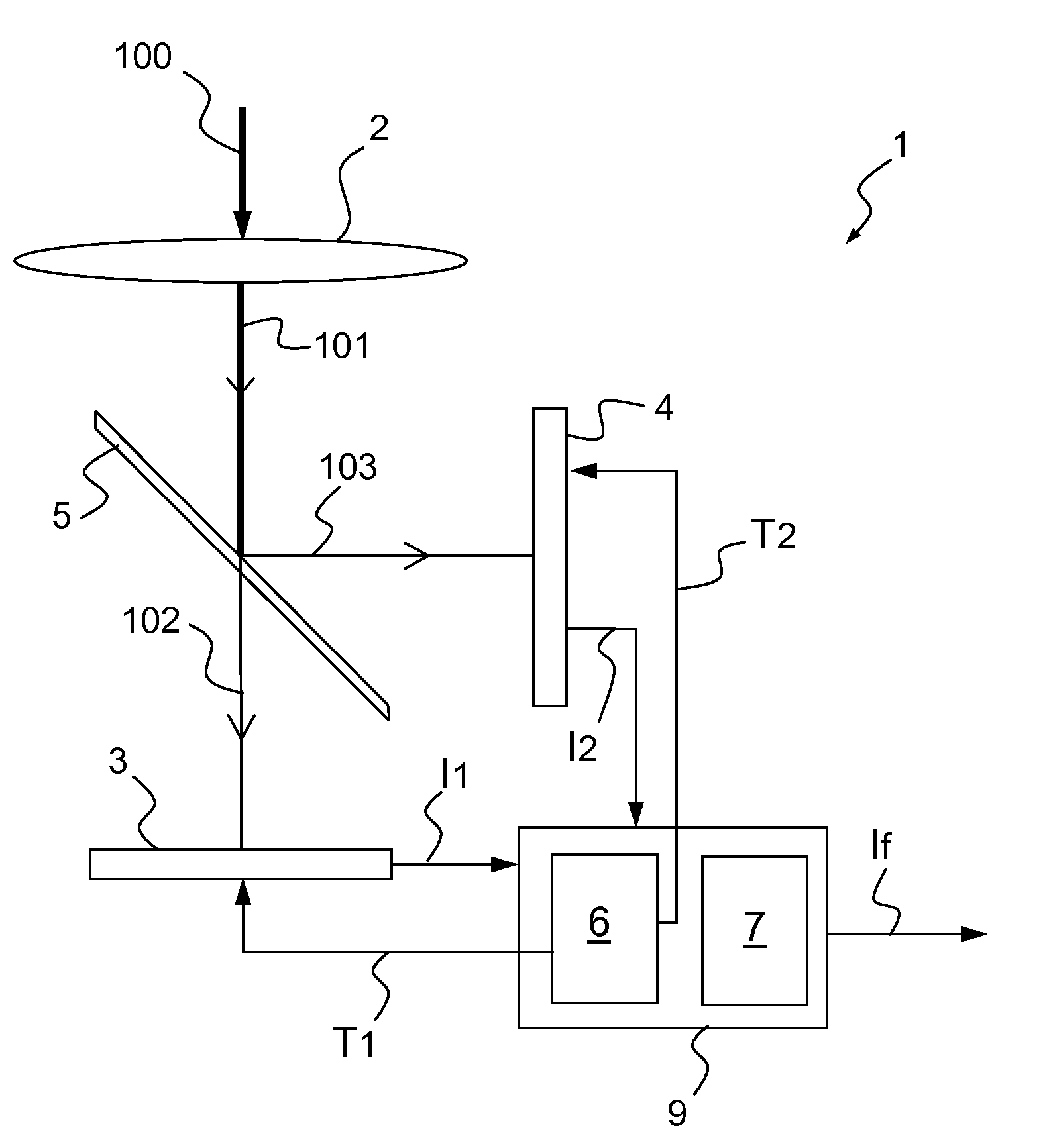
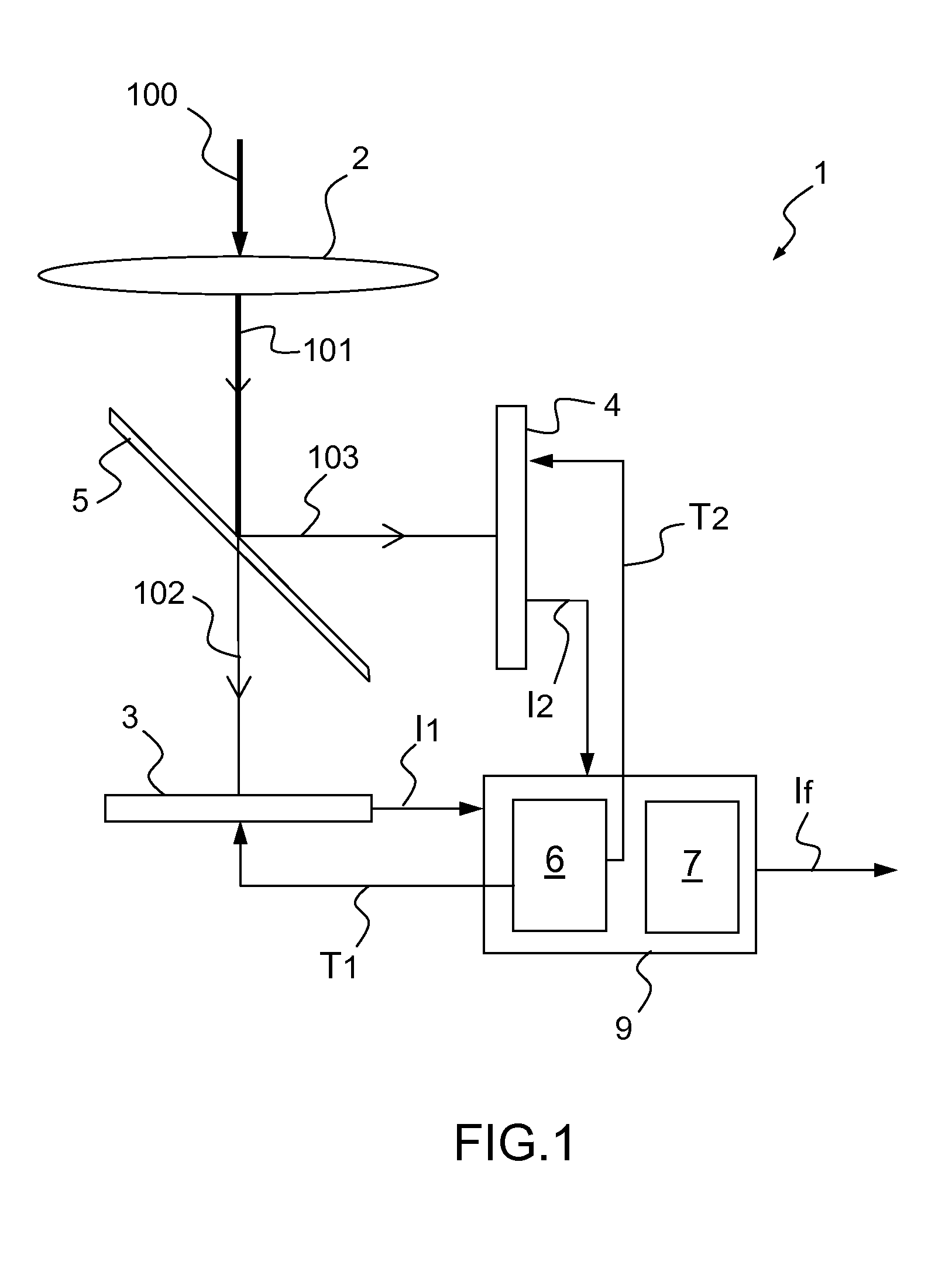
[0080]In a first embodiment, the separation means 5 are configured in such a manner that the difference between the first fraction 102 and the second fraction 103 is the maximum difference that does not result in any distortion being generated in the final image.

[0081]Typically, the second fraction 103 is in the range between a lower fraction (greater than 0%) and 10% of the irradiance of the beam 101. Consequently, the first fraction 102 is in the range between 90% of the irradiance coming from the focussing optics and an upper fraction corresponding to the difference between 100% and the lower fraction.

[0082]The lower fraction and the upper fraction are the respective high and low limits beyond which the final image exhibits distortions.

[0083]The applicant has observed that the maximum dynamic range is obtained with a first fraction 102 of 95% and a second fraction 103 of 5% of the irradiance of the beam 101.

[0084]In this configuration, the sensor illuminated by the weakest irradi...

second embodiment

[0085]In a second embodiment, the first fraction of the irradiance is approximately equal to 50%. The term “approximately equal to 50%” is understood to mean that the second fraction is either equal to 50% or in the range between 20% and 50% of the irradiance coming from the focussing optics. This second case (first fraction in the range between 50 and 80%) is valid when the first sensor is the low-luminance sensor.

[0086]This embodiment is advantageous when it is desired to mainly gain in resolution of the system while at the same time conserving the possibility of increasing the dynamic range acceptable by the system in the case of presence of dazzling light in the field. As a result, a system having a better resolution than one using a single sensor is obtained. For example, in the case where the two sensors 3, 4 are offset with respect to one another by half a pixel along the rows and along the columns of pixels, an image having a resolution four times higher than the image comin...


PUM


Abstract

An image acquisition system comprises: a single set of focussing optics focussing an incident beam from a scene to be imaged on a first sensor and a second sensor exhibiting identical spectral response curves; followed by separation means separating the irradiance of the beam coming from the focussing optics into first and second predetermined fractions, the separation means orienting the first fraction towards the first sensor and the second fraction towards the second sensor; control means for controlling a first acquisition time of the scene to be imaged by the first sensor to obtain a first image and/or a second acquisition time of the scene to be imaged by the second sensor to obtain a second image; and merging means that merge the first image coming from the first sensor and the second image coming from the second sensor to generate a final image.

Description

CROSS-REFERENCE TO RELATED APPLICATION[0001]This application claims priority to foreign French patent application No. FR 1004870, filed on Dec. 14, 2010, the disclosure of which is incorporated by reference in its entirety.FIELD OF THE INVENTION[0002]The invention relates to systems for real-time acquisition of image sequences. It is desirable that image acquisition systems record images having the widest dynamic range possible. In other words, the aim is to produce image acquisition systems that are sensitive in the presence of a low level of illumination and are capable of receiving very bright images without saturation. Typically, it is desirable that image sequence acquisition systems or images having a dynamic range equal to at least 120 dB may be obtained.BACKGROUND[0003]Several solutions have been investigated for obtaining a wide dynamic range. First of all, there exist solutions using a single sensor equipped with means for image capture with high dynamic range. These syste...

Claims


Application Information

Patent Timeline
Patent Type & Authority Applications(United States)
IPC IPC(8): H04N5/265
CPCH04N5/235H04N5/35554H04N5/2355H04N23/70H04N23/741H04N25/583
Inventor GROSSETETE, MATTHIEUEBERT, JEAN-CLAUDEFRANCOIS, JEAN-MICHEL
Owner THALES SA
Why Eureka
Try Eureka