Deep water fishing rod and electric reel

a technology for electric reels and fishing rods, applied in the field of fishing, can solve the problems of inability to address friction, inability to provide ready access for retrieving fish, and modification of conventional fishing equipment, and achieve the effect of facilitating rotation and removal

Active Publication Date: 2012-10-18
LINDGREN PETER B
View PDF0 Cites 4 Cited by
  • Summary
  • Abstract
  • Description
  • Claims
  • Application Information

AI Technical Summary

Benefits of technology

[0019]An objective of the instant invention is to disclose a deep water rod that eliminates line guides.
[0035]Yet another objective is to provide a cone shaped attachment of the reel to the reel base to the rod, allowing ease of rotation and removal as needed.

Problems solved by technology

The rod employs the use of line guides along the length of the rod and thus fails to address the friction induced by the line guides, or the friction induced from a tip mounted line guide should an off angle pull occur.
However, modification of conventional fishing equipment can not address the aforementioned problems due to inherent limitations such as the need for a plurality of guide rollers.
The end of the rod will have a pulley placed underneath the rod which is wasteful in vertical height and does not provide ready access for retrieving fish.
Finally, because deep water electric reels and rods are larger than most hand cranks, they will not fit in a standard rod and reel storage holder.

Method used


Image

  • Deep water fishing rod and electric reel
  • Deep water fishing rod and electric reel
  • Deep water fishing rod and electric reel

Examples


Embodiment Construction

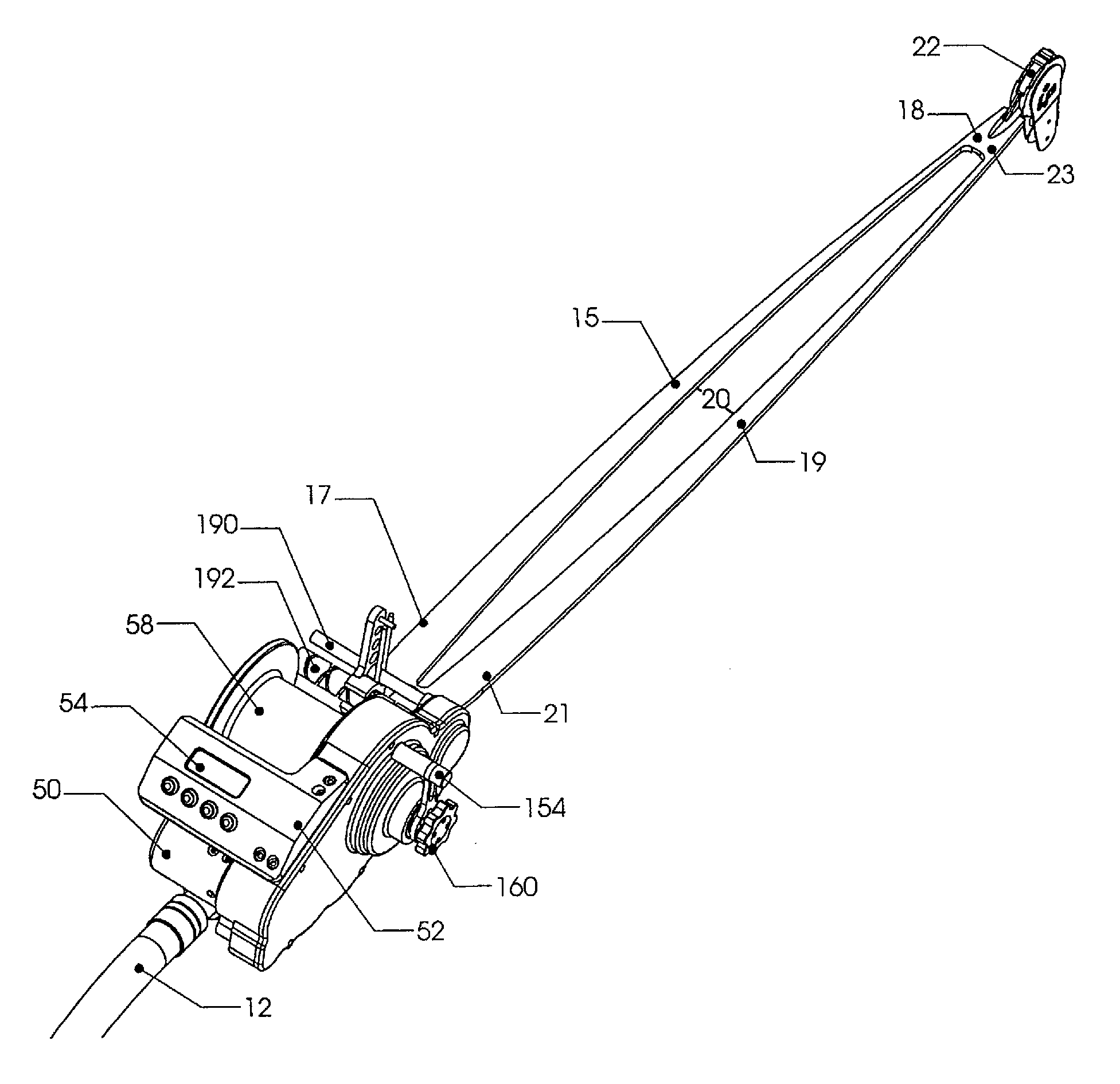
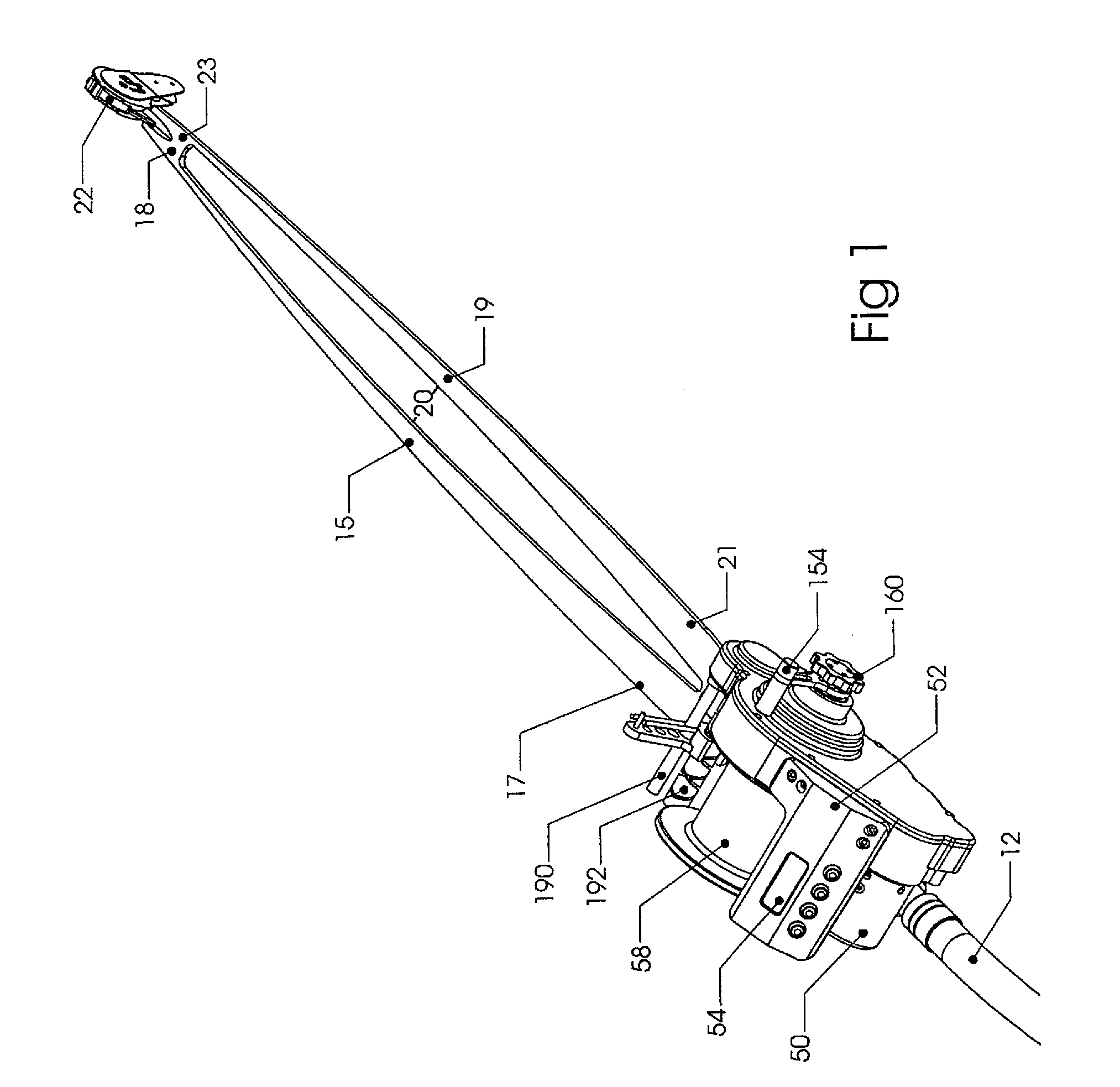
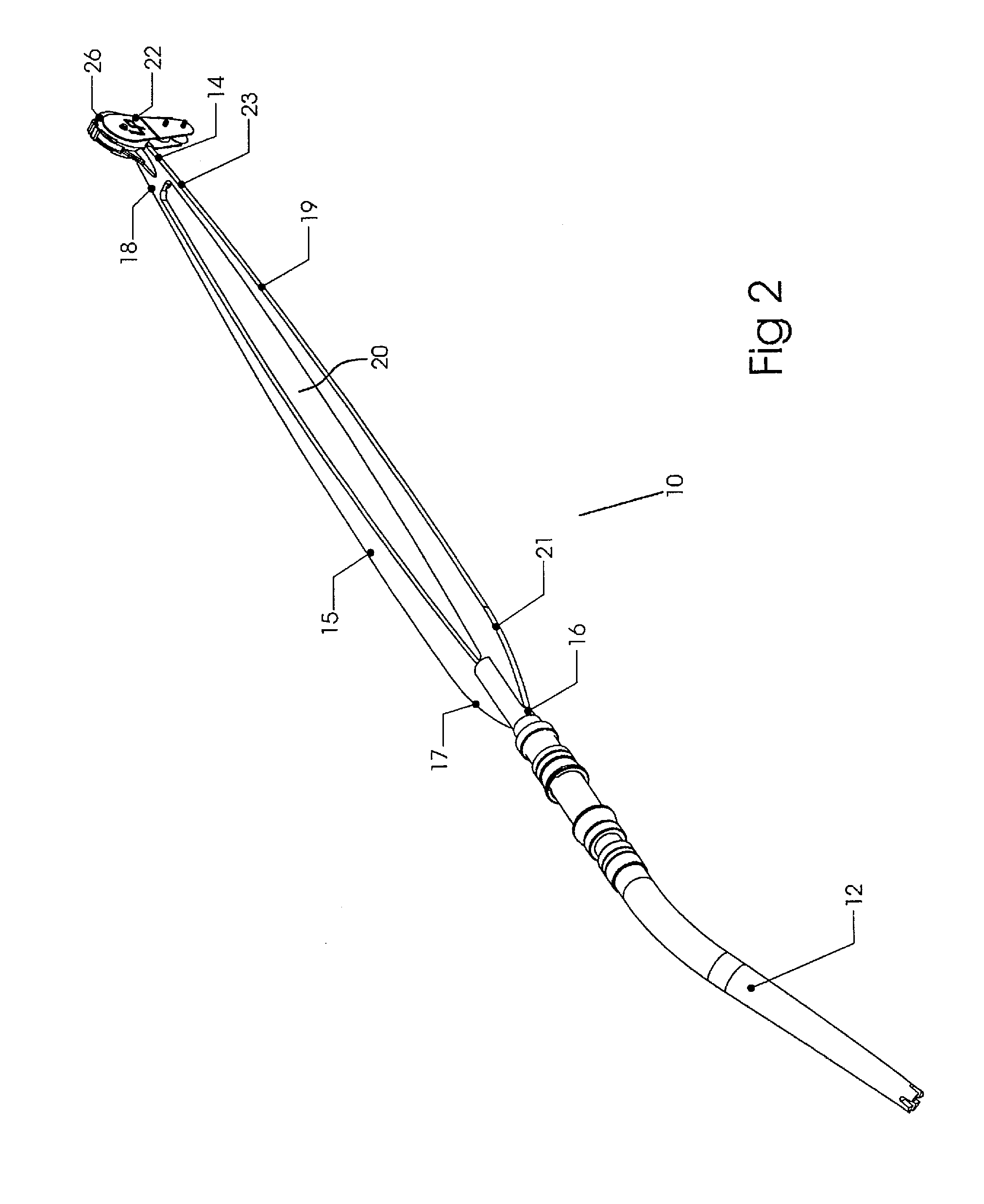
[0054]Now referring to the Figures, set forth is a fishing rod 10 of the instant invention defined at one end by a rod holder butt 12 and at the opposite end by a swivel guide tip 14. The rod 10 further includes a flexible rod portion 24 defined by a proximal end 16 and distal end 18 formed into a wishbone shape having minimum thickness. The flexible rod portion 24 includes a first elongated member 15 having a proximal end 17, a distal end 18 forming a length therebetween. A second elongated member 19 has a proximal end 21, a distal end 23 forming a length therebetween. The proximal ends 17 and 21 of the elongated members are connected 16 to the reel butt 12. The distal end 18 of the first elongated member 15 is connected to the distal end 23 of the second elongated member 19 along end section 14 whereby the elongated members 15 and 19 are spaced apart forming an opening 20. A fishing guide means 22 is positioned at the distal ends 14 of the elongated members for directional placeme...


PUM


Abstract

A rod and reel assembly for deep water fishing. The rod employs a structure that eliminates the need for line guides along the length of the structure by use of a swivel guide that maintains the line between two rod members. The swivel roller is placed at the distal end of the structure allowing fishing line deployed from a mounted reel to the swivel roller to pass unobstructed through the structure. Also disclosed is an electric reel that includes a cantilever spool having an enlarged interior allowing hand control of free spooling. A two stage drag system employs a first set of springs to allow hands free spooling with minimal drag and a second set of springs for proper setting for the fish hauling.

Description

PRIORITY CLAIM[0001]This application is a continuation of U.S. patent application Ser. No. 12 / 505,099, filed Jul. 17, 2009, which is a continuation-in-part of U.S. patent application Ser. No. 11 / 355,911, filed Feb. 16, 2006, now abandoned, which claims a priority date of Feb. 17, 2005 based upon U.S. Provisional Patent Application No. 60 / 654,386, the contents of all of these applications are incorporated herein by reference.FIELD OF THE INVENTION[0002]The field of the invention is related to fishing and in particular to a rod and electric reel for use in deep sea fishing.BACKGROUND OF THE INVENTION[0003]Fishing in water depths between 300 and 2000 feet is known as deep water fishing. Deep water fishing is considered one of the most productive types of fishing due to the abundance of fish at these lower depths. However, the ability to fish in deep water requires special equipment that is typically expensive, complicated, and otherwise unusable by recreational fisherman.[0004]The tact...

Claims


Application Information

Patent Timeline
Patent Type & Authority Applications(United States)
IPC IPC(8): A01K87/04A01K87/02A01K97/10
CPCA01K87/00A01K87/04A01K89/0155A01K89/033A01K89/017A01K89/01912
Inventor LINDGREN, PETER B.
Owner LINDGREN PETER B
Why Eureka
Try Eureka