

RF signal generation circuit and wireless transmitter
a signal generation circuit and wireless transmitter technology, applied in the direction of generating/distributing signals, pulse techniques, instruments, etc., can solve the problems of power consumption of power amplifiers, achieve good noise characteristics, reduce thermal loss, and reduce overlap of currents
- Summary
- Abstract
- Description
- Claims
- Application Information
AI Technical Summary
Benefits of technology
Problems solved by technology
Method used
Image

Examples
first embodiment
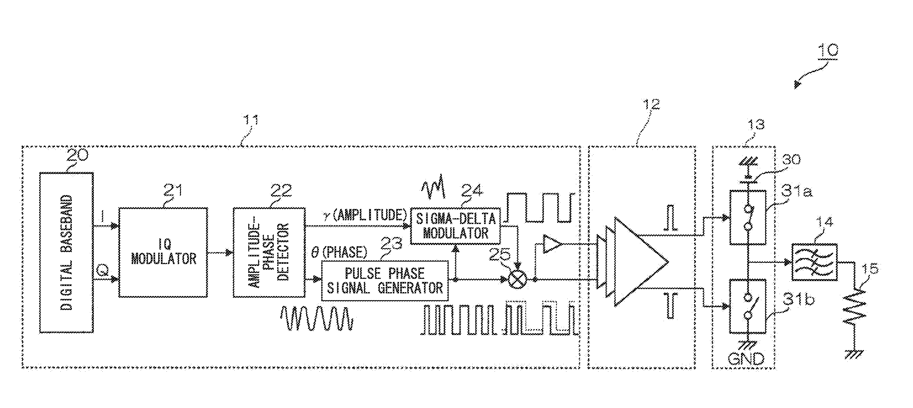
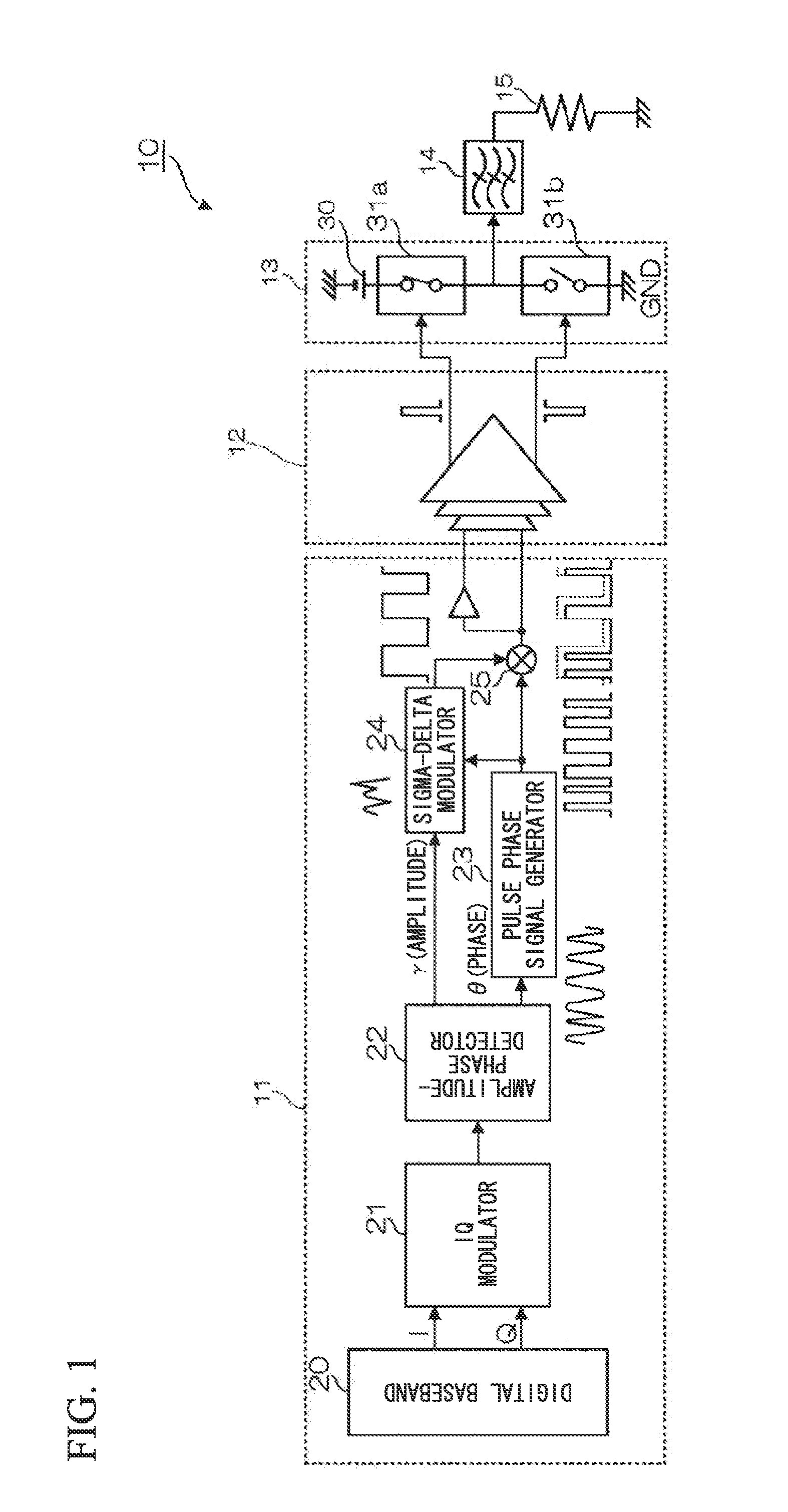
[0050]FIG. 1 is a block diagram showing the constitution of a wireless transmitter 10 according to a first embodiment of the present invention. The wireless transmitter 10 includes an RF signal generation circuit 11, a driver amplifier 12, and a D-class amplifier 13. The RF signal generation circuit 11 includes a digital baseband 20, an IQ modulator 21, an amplitude-phase detector 22, a pulse phase signal generator 23, a sigma-delta modulator 24, and a mixer 25.
[0051]The IQ modulator 21 converts an orthogonal wireless signal, generated by the digital baseband 20, into an RF signal. The amplitude-phase detector 22 divides an RF signal to extract an amplitude signal γ and a phase signal θ. The amplitude signal γ is supplied to the sigma-delta modulator 24 while the phase signal θ is supplied to the pulse phase signal generator 23.
[0052]The pulse phase signal generator 23 generates a pulse phase signal which is High when the phase signal θ lies between 0° and 180° but which is Low when...
second embodiment
[0089]Next, a second embodiment of the present invention will be described.
[0090]FIG. 9 is a block diagram showing the constitution of a wireless transmitter 100 according to a second embodiment of the present invention. In FIG. 9, the constituent parts identical to those shown in FIG. 1 are denoted using the same reference signs; thus, their descriptions will be omitted. Compared to the wireless transmitter 10 of the first embodiment, the wireless transmitter 100 of the second embodiment replaces the RF signal generation circuit 11 with an RF signal generation circuit 110. The RF signal generation circuit 110 has the same function as the RF signal generation circuit 11; but it carries out a different signal generating process. The following description refers to the constitution and the operation of the RF signal generation circuit 110.
[0091]In FIG. 9, the RF signal generation circuit 110 includes the digital baseband 20, an amplitude detector 26, a phase detector 27, the pulse pha...
third embodiment
[0101]Next, a third embodiment of the present invention will be described.
[0102]FIG. 12 is a block diagram showing the constitution of a wireless transmitter 200 according to a third embodiment of the present invention. In FIG. 12, the constituent elements identical to those shown in FIG. 1 are denoted using the same reference signs; hence, their descriptions will be omitted. Compared to the first embodiment shown in FIG. 1, the third embodiment replaces the RF signal generation circuit 11 with an RF signal generation circuit 111, replaces the driver amplifier 12 with a driver amplifier 120, and replaces the class-D amplifier 13 with a class-D amplifier 130. Additionally, a decoder is interposed between the RF signal generation circuit 111 and the driver amplifier 120. The RF signal generation circuit 111 replaces the sigma-delta modulator 24 of the RF signal generation circuit 11 with a sigma-delta modulator 241.
[0103]FIG. 13 is a circuit diagram showing the constitution of the sig...
PUM
 Abstract
Description
Claims
Application Information