
Display Apparatus

a technology for display apparatuses and display cases, which is applied in the field of display apparatuses, can solve the problems of reducing the thickness of lcd or changing the design, attracting much attention, and limiting the development of new designs of display apparatuses, so as to enhance the sense of beauty, prevent light leakage, and minimize the thickness

Active Publication Date: 2012-10-18
LG DISPLAY CO LTD
View PDF3 Cites 33 Cited by
  • Summary
  • Abstract
  • Description
  • Claims
  • Application Information

AI Technical Summary

Benefits of technology

[0009]An aspect of the present invention is directed to provide a display apparatus which does not use some elements of cases and set cover members necessary for producing the display apparatus and thus can minimize a thickness and enhance a sense of beauty with an innovative design.
[0010]Another aspect of the present invention is directed to provide a display apparatus which can prevent light leakage due to the non-movement of a display panel that is caused by removing some elements of cases and set cover members.
[0012]To achieve these and other advantages and in accordance with the purpose of the invention, as embodied and broadly described herein, there is provided a display apparatus including: a display panel; a panel supporting member disposed to have a side inserting space, and supporting a rear edge of the display panel; an adhesive member disposed at the panel supporting member, and coupling the display panel and the panel supporting member; a guide frame supporting the panel supporting member; and a cover member inserted into the side inserting space of the panel supporting member, and surrounding a side surface of the guide frame, thereby enabling movement of the panel supporting member.

Problems solved by technology

However, among such flat panel display apparatuses, Liquid Crystal Display are easily manufactured, have good drivability of drivers, realize a high-quality image, and thus are attracting much attention.
Due to these reasons, there are limitations in slimming display apparatus and developing the new designs of the display apparatus.
As described above, display apparatus of the related art necessarily use the front set cover and rear set cover as well as the lower case and front case, and consequently, there are limitations in reducing the thicknesses of LCD or changing the designs thereof.
Due to this reason, the thicknesses of display apparatus inevitably become thicker, and moreover, the border widths of the display apparatus enlarge.
In addition, it is difficult to realize various innovative designs due to a step height in a border portion.

Method used


Image

  • Display Apparatus
  • Display Apparatus
  • Display Apparatus

Examples


first embodiment

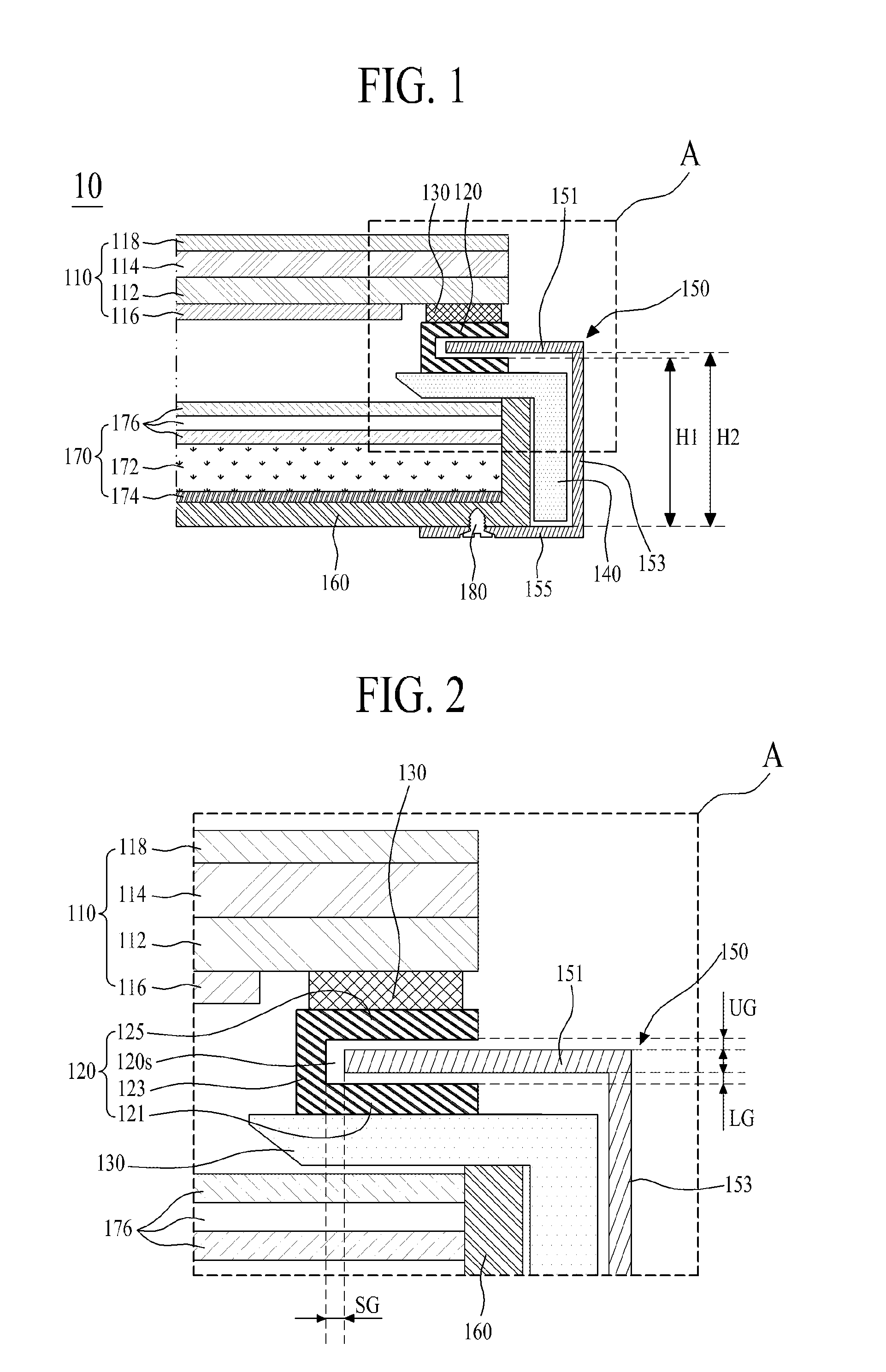
[0050]FIG. 1 is a view schematically illustrating a display apparatus according to the present invention. FIG. 2 is an enlarged view of a portion A of FIG. 1.

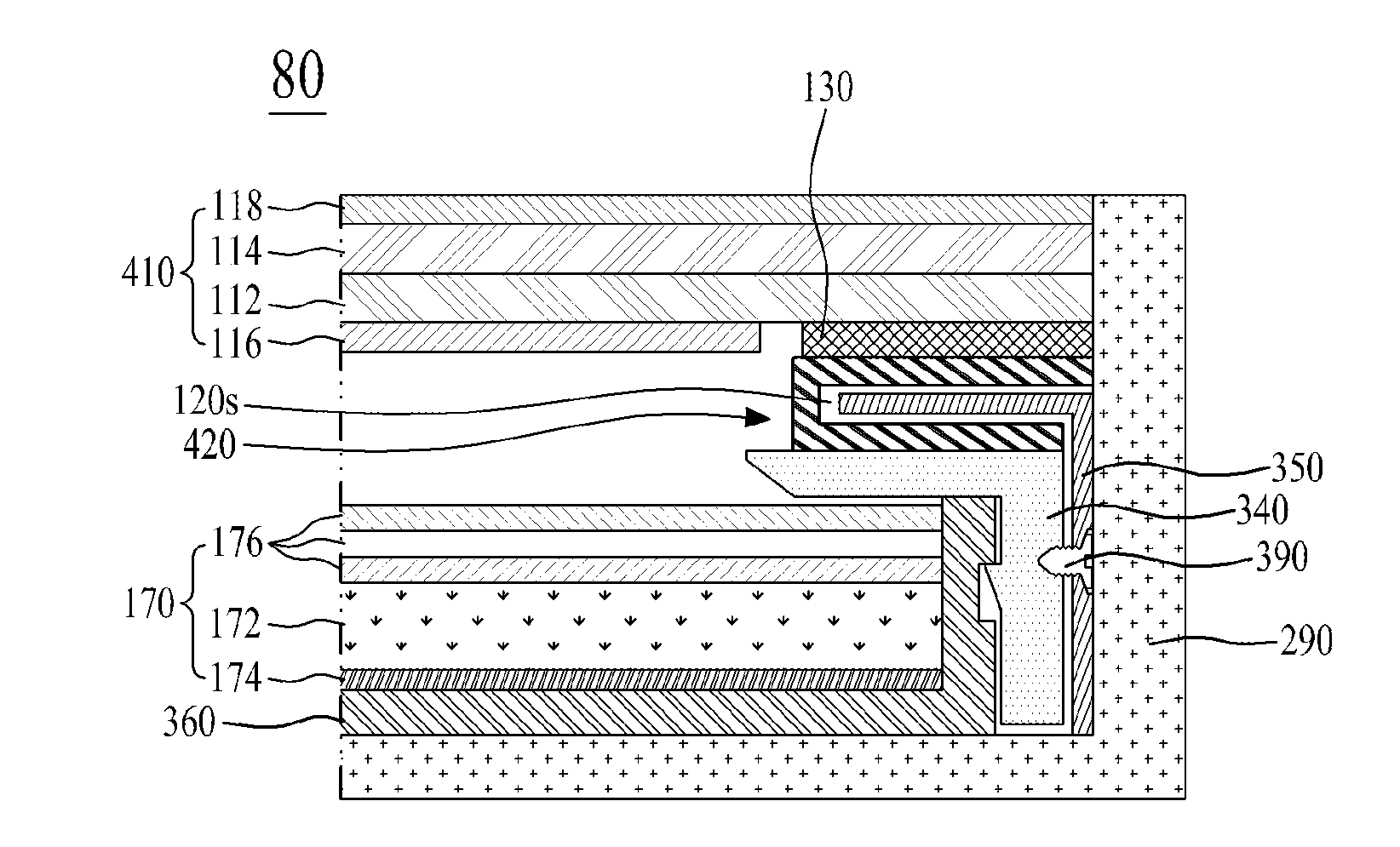
[0051]Referring to FIGS. 1 and 2, a display apparatus 10 according to the first embodiment of the present invention includes a display panel 110, a panel supporting member 120 that is formed to have a side inserting space 120s and supports a rear edge of the display panel 110, an adhesive member 130 that is formed at the panel supporting member 120 and couples the display panel 110 and the panel supporting member 120, a guide frame 140 that supports the panel supporting member 120, and a cover member 150 that is inserted into the side inserting space 120s of the panel supporting member 120 and disposed to surround a side surface of the guide frame 140 so as to enable the movement of the panel supporting member 120.

[0052]The display panel 110 may be a liquid crystal display panel or an organic light emitting display panel that i...

second embodiment

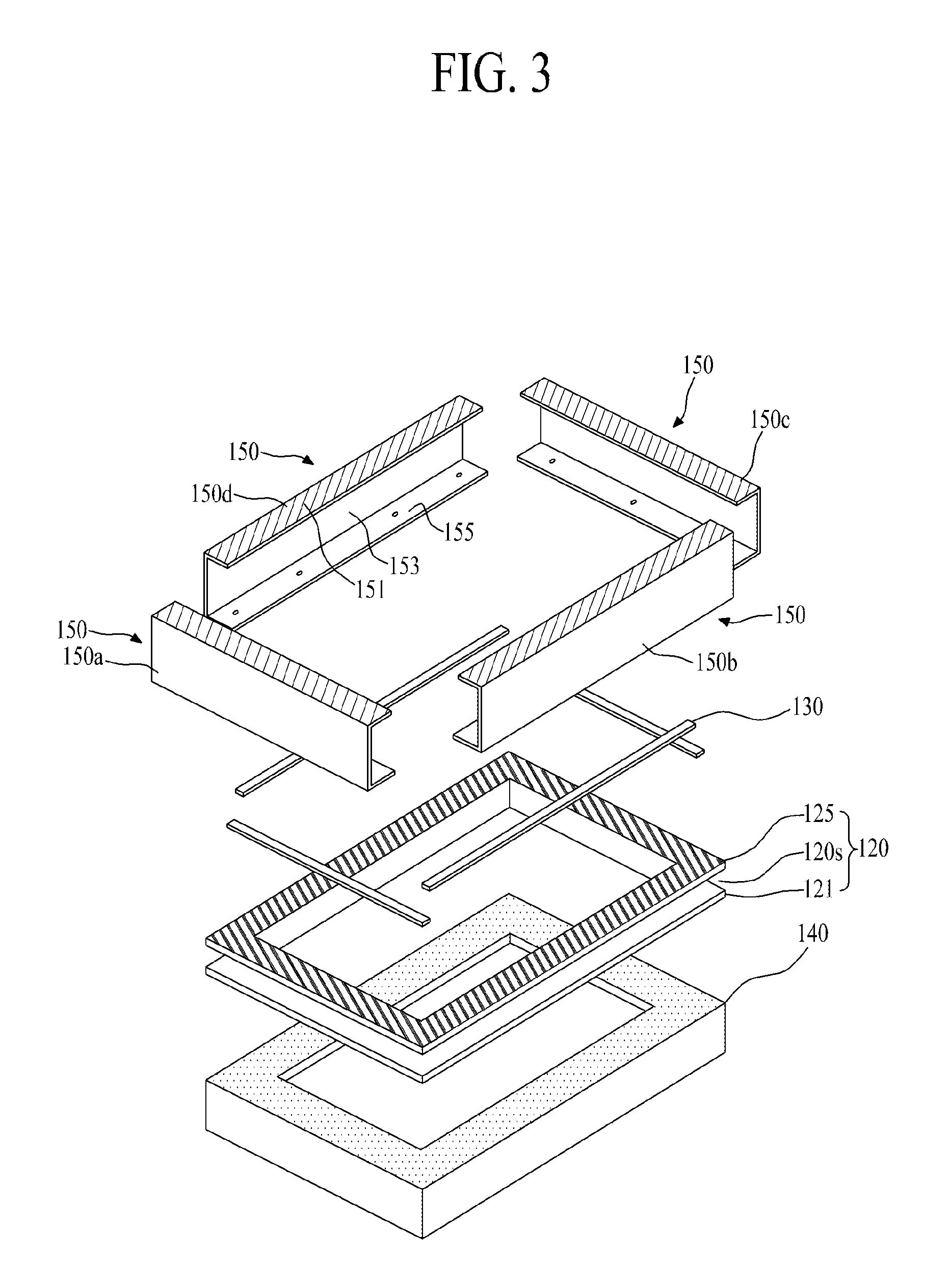
[0063]A panel supporting member 120 as illustrated in FIG. 5, includes first to fourth supporting brackets 120a to 120d that are coupled to the rear edge portions of respective long sides and short sides of the display panel 110, and supported by the guide frame 140.

[0064]Each of the first to fourth supporting brackets 120a to 120d is formed to include the frame disposing part 121, vertical portion 123, and panel disposing part 125, and disposed at the guide frame 140. Therefore, each of the first to fourth supporting brackets 120a to 120d disposed at the guide frame 140 has a tetragonal frame shape.

[0065]The panel supporting member 120 according to the second embodiment, as illustrated in FIG. 6, may further include a plurality of slits 127a and 127b that are formed at certain intervals, at the frame disposing part 121 and / or panel disposing part 125 of each of the first to fourth supporting brackets 120a to 120d.

[0066]Each of the slits 127a and 127b divides the frame disposing p...

third embodiment

[0067]A panel supporting member 120 as illustrated in FIG. 7, includes a plurality of supporting brackets 128 that partially support the rear edge portions of respective long sides and short sides of the display panel 110.

[0068]Each of the supporting brackets 128 is formed to include the frame disposing part 121, vertical portion 123, and panel disposing part 125, and disposed at certain intervals at the guide frame 140.

[0069]When the display panel 110 is a liquid crystal display panel, in performing the high temperature deformation of the display panel 110, light leakage such as the spot of the display panel 110 occurs by the direct contact of the display panel 110 and both side ends of each of the supporting brackets 128, and the degree of deformation of the display panel 110 that is concentrated on both side ends of each of the supporting brackets 128. To prevent such limitations, as illustrated in FIG. 9, each supporting bracket 128 of FIG. 7 may further include a pair of adhes...


PUM


Abstract

Disclosed is a display apparatus which does not use some elements of cases and set cover members necessary for producing the display apparatus and thus can minimize a thickness and enhance a sense of beauty with an innovative design. The display apparatus includes a display panel, a panel supporting member, an adhesive member, a guide frame, and a cover member. The panel supporting member is disposed to have a side inserting space, and supports a rear edge of the display panel. The adhesive member is disposed at the panel supporting member, and couples the display panel and the panel supporting member. The guide frame supports the panel supporting member. The cover member is inserted into the side inserting space of the panel supporting member, and surrounds a side surface of the guide frame, thereby enabling movement of the panel supporting member.

Description

CROSS-REFERENCE TO RELATED APPLICATIONS[0001]This application claims the benefit of the Korean Patent Application No. 10-2011-0035888 filed on Apr. 18, 2011, which is hereby incorporated by reference as if fully set forth herein.BACKGROUND[0002]1. Field of the Invention[0003]The present invention relates to a display apparatus, and more particularly, to a display apparatus which does not use some elements of cases and set cover members necessary for producing the display apparatus and thus can minimize a thickness and enhance a sense of beauty with an innovative design.[0004]2. Discussion of the Related Art[0005]Recently, flat panel display apparatuses that can decrease a weight and a volume corresponding to the limitations of Cathode Ray Tubes (CRTs) are being developed. Liquid Crystal Display (LCD), Plasma Display Panels (PDPs), Field Emission Display (FED), and light emitting display are actively being researched as flat type display apparatuses. However, among such flat panel di...

Claims


Application Information

Patent Timeline
Patent Type & Authority Applications(United States)
IPC IPC(8): G09F13/04H05K5/03
CPCG06F1/1637H05K5/02G06F2200/1612G06F1/1601G02F1/133308G02F1/133317H05K5/03H05K5/0004H05K5/0017
Inventor LEE, HYUNSEOKPARK, SANGRYEON
Owner LG DISPLAY CO LTD
Features
  • Generate Ideas
  • Intellectual Property
  • Life Sciences
  • Materials
  • Tech Scout
  • Unparalleled Data Quality
  • Higher Quality Content
  • 60% Fewer Hallucinations
Learn More