Fault Current Limited System with Current Splitting Device

a current splitting device and fault current limiter technology, applied in the field of fault current limiters, can solve the problems of large load instantaneously appearing in the circuit, undesirable surge of current, and system fault current, and achieve the effect of reducing the fault current load, and reducing the cost and physical size of the fcl

Inactive Publication Date: 2012-10-18
VARIAN SEMICON EQUIP ASSOC INC
View PDF5 Cites 45 Cited by
  • Summary
  • Abstract
  • Description
  • Claims
  • Application Information

AI Technical Summary

Benefits of technology

[0010]During steady state operation of the FCL system, the current splitting device splits current into two branches that flow through the conductive windings in opposite directions to produce a net zero or negligible magnetic field, thereby resulting in a negligible equivalent or net impedance in the circuit. The reactance of the first winding is therefore substantially negated by the oppositely-directed reactance of the second winding. Thus, by selecting first and second windings having appropriate numbers of turns, a predetermined portion of steady state current can be routed through the variable shunt. The steady state current load on the FCL is thereby reduced relative to conventional FCL systems. The cost and physical size of the FCL can therefore also be reduced.
[0011]Upon th...

Problems solved by technology

A fault current is an abnormal current in an electrical system that may result from a fault in the system, such as a short circuit.
A fault current may arise in a system due to any number of events or failures, such as power lines or other system components being damaged by severe weather (e.g. lightning strikes).
When such a fault occurs, a large load can instantaneously appear in the circuit.
This surge of current is undesirable because it can damage the load which may be, for example, the network itself or equipment connected to the network.
Although fixed shunt FCL systems such as the one described above can be very effective for limiting fault currents, a significant drawback of such systems is that the FCL must be configured to carry all of the anticipated steady state current o...

Method used


Image

  • Fault Current Limited System with Current Splitting Device
  • Fault Current Limited System with Current Splitting Device
  • Fault Current Limited System with Current Splitting Device

Examples


Embodiment Construction

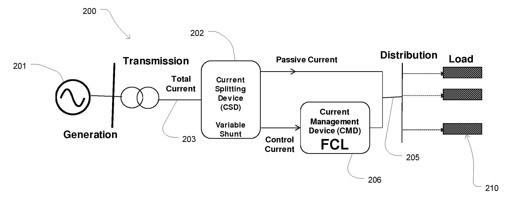
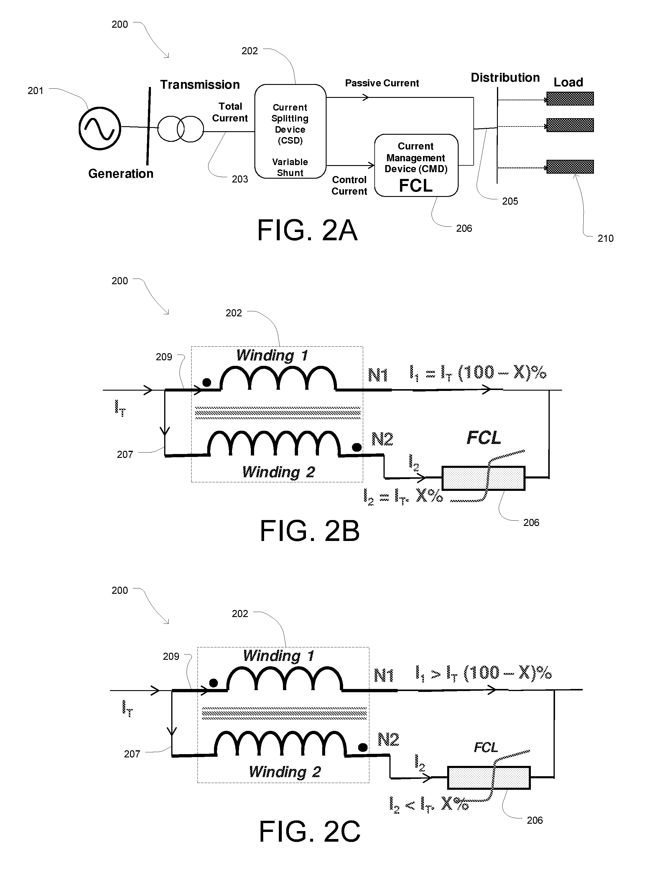
[0025]FIGS. 2A-2C and 4 illustrate circuit diagrams of a fault current limiter (FCL) system 200 consistent with an embodiment of the present disclosure. In particular, the FCL system 200 may comprise a current splitting device 202 coupled with a FCL 206. FIG. 2B illustrates the FCL system 200 during steady state operation and FIG. 2C illustrates the FCL system 200 during a fault condition as further described below.

[0026]The FCL system 200 can be electrically connected in series intermediate an AC power source 201 and one or more electrical loads 210 via conductors 203 and 205. It will be appreciated by those of ordinary skill in the art that the FCL system 200 can be implemented in a variety of other applications and power system configurations in which fault current limiting is desirable. The particular power system depicted in FIGS. 2A-2C is therefore shown by way of example only and is not intended to be limiting.

[0027]It is contemplated that various types of FCLs can be impleme...


PUM


Abstract

A fault current limiter system including a fault current limiter and a variable shunt current splitting device. The current splitting device includes first and second conductive windings, wherein the first conductive winding is connected in parallel with the fault current limiter and is configured to carry current in a first direction. The second conductive winding is electrically connected in series with the fault current limiter and is configured to carry current in a second direction opposite to the first direction so that the reactance of the first winding is negated by the reactance of the second winding during steady state operation of the fault current limiter system. Thus, a first portion of a steady state current is conveyed through the fault current limiter and a second portion of the current is conveyed through the current splitting device. The steady state current load, on the fault current limiter is thereby reduced.

Description

CROSS-REFERENCE TO RELATED APPLICATIONS[0001]This is a non-provisional of pending U.S. provisional patent application Ser. No. 61 / 475,976, filed Apr. 15, 2011, the entirety of which application is incorporated herein by reference.FIELD OF THE DISCLOSURE[0002]This disclosure relates to fault current limiters, and more particularly to a fault current limiter system having a fault current limiter and a variable shunt current splitting device configured to reduce the steady state current flowing through the fault current limiter.BACKGROUND OF THE DISCLOSURE[0003]A fault current limiter (FCL) is a device that limits fault currents, typically in a power system. Various types of FCLs have been developed over the last several decades, including superconducting fault current limiters (SCFCLs), solid state fault current limiters, inductive fault current limiters, as well as other varieties that are well known in the art. A power system in which a FCL is implemented may include generation, tra...

Claims


Application Information

Patent Timeline
IPC IPC(8): H02H9/08H01L39/02
CPCH02H9/023H02H9/021Y02E40/69Y02E40/60
Inventor TEKLETSADIK, KASEGN
Owner VARIAN SEMICON EQUIP ASSOC INC
Why Eureka
Try Eureka