Vertebroplasty Curved Needle

Inactive Publication Date: 2012-10-18
DEPUY SYNTHES PROD INC
View PDF7 Cites 8 Cited by
  • Summary
  • Abstract
  • Description
  • Claims
  • Application Information

AI Technical Summary

Benefits of technology

[0011]One primary advantage of the present invention is its ability to create a central cavity in a vertebral body (or to centrally deliver bone cement) through a unipedicular approach.
[0012]The present invention is a curved needle having increased rigidity in its flexible end when the end is disposed in its straight position. This increased rigidity is due to a novel cable tensioning mechanism and to a segmented tube design (as opposed to the conventional longitudinally-slotted tube design).
[0013]The curved needle of the present invention also displays decreased fatigue stress in the flexible end during bending (in comparison to slotted tube designs) because no component of the tube of the present invention is internally bent. This is due to use of a cable and separate, nested tube segments in the present invention. Therefore, the present invention displays an increased durability of the flexible tubular end.

Problems solved by technology

Because the pedicle are present at the lateral edges of the vertebral body, pedicle-based delivery has difficulty in delivering material to the central (mid-line) region of the vertebral body.
One proposed solution is to fill the central region from a lateral needle tip—however, this approach may lead to overfilling and leak

Method used


Image

  • Vertebroplasty Curved Needle
  • Vertebroplasty Curved Needle
  • Vertebroplasty Curved Needle

Examples


Example

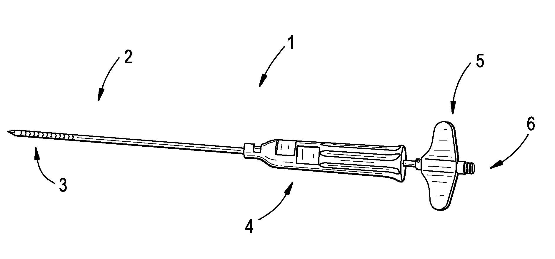
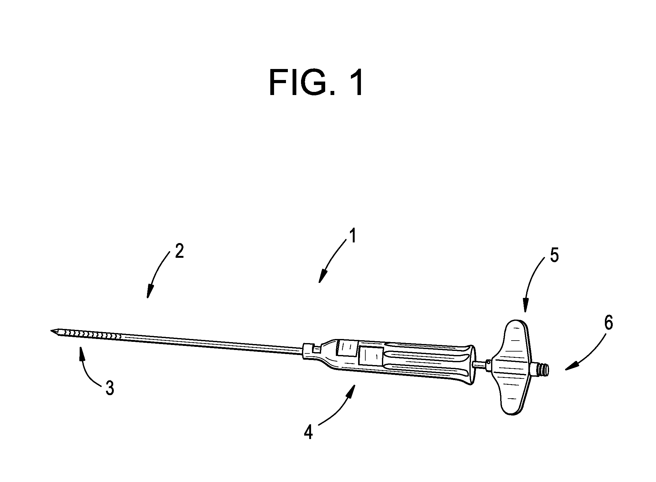
[0058]Now referring to FIG. 1, there is provided a curved needle assembly 1. The instrument comprising: tube assembly 2, shrink tubing3, handle 4, driving handle 5, and luer fitting 6.

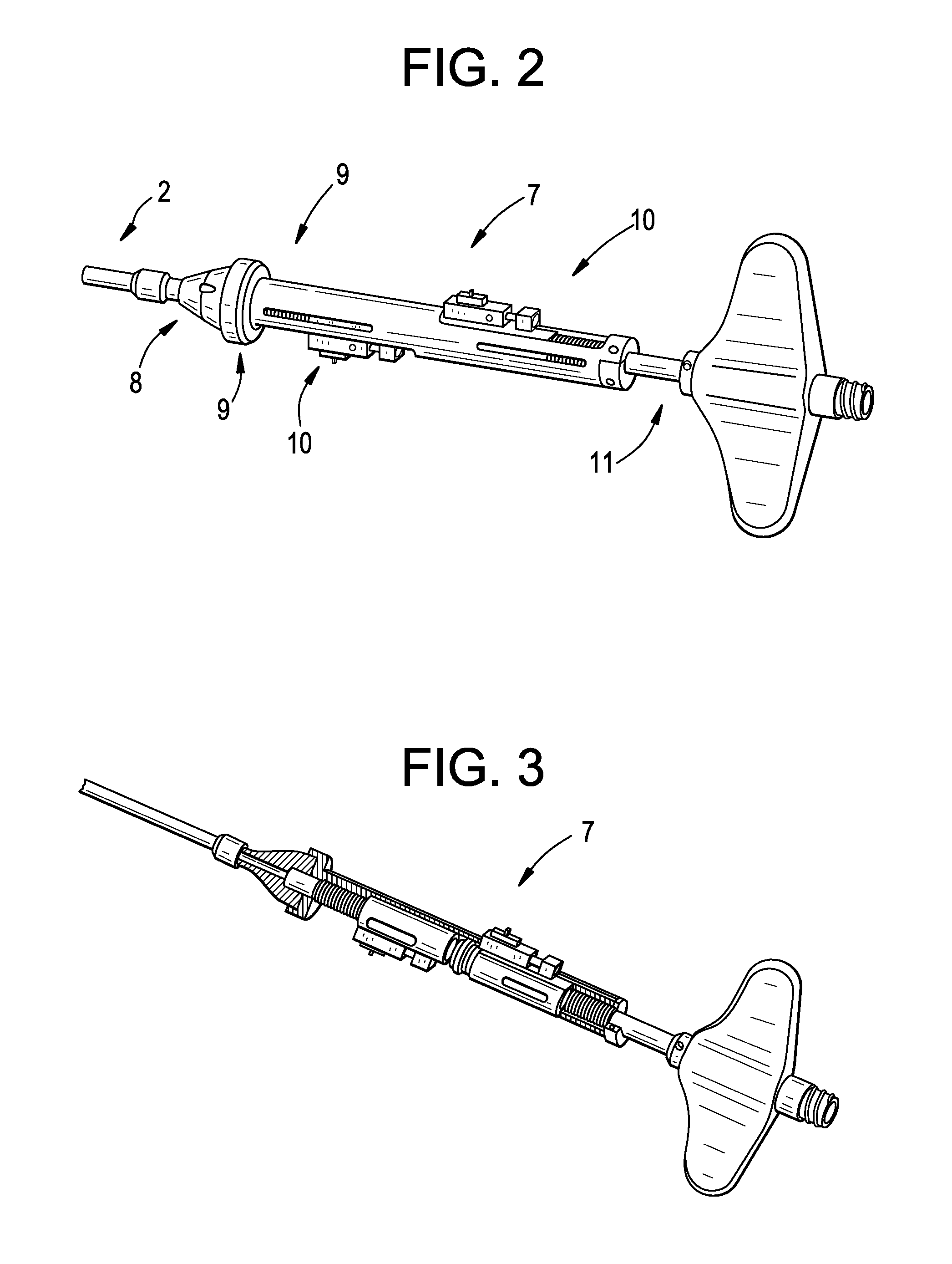
[0059]Now referring to FIG. 2, the driving mechanism 7 comprises a split wire funnel 8, split handle inserts 9, left and right cable couplings 10 and driving shaft 11.

[0060]FIG. 3 shows the driving mechanism without a cover.

[0061]FIG. 4 illustrates the flexible distal end portion of the steerable needle 13, which comprises a top segment 14, intermediate segments 15 and bottom segment 16. The flexible portion acts via unidirectional action, as adjacent segments define a gap 17 therebetween. During actuation of the flex, these gaps close to produce the concave side of the flex.

[0062]FIG. 5a discloses a distal tip segment 14 comprising outer shell 18, pressed or welded insert 19, central hole 20 and a side hole for injecting cement 21. FIG. 5b discloses one preferred distal tip segment 101 having an integ...


PUM


Abstract

Devices, systems and methods for delivering a curable, stabilizing material into a central region of a bone structure. Precise placement of the curable substance into a central region of a bone structure through a unipedicular approach. One primary advantage is its ability to create a central cavity in a vertebral body (or to centrally deliver bone cement) through a unipedicular approach. A curved needle having increased rigidity in its flexible end when the end is disposed in its straight position. This increased rigidity is due to a novel tensioning mechanism and to a segmented tube design (as opposed to the conventional longitudinally-slotted tube design).

Description

BACKGROUND OF THE INVENTION[0001]In vertebroplasty, the surgeon seeks to treat a compression fracture of a vertebral body by injecting bone cement such as PMMA into the fracture site. One clinical report describes mixing two PMMA precursor components (one powder and one liquid) in a dish to produce a viscous bone cement; filling 10 cc syringes with this cement, injecting it into smaller 1 cc syringes, and finally delivering the mixture into the desired area of the vertebral body through needles attached to the smaller syringes.[0002]This injection of the stabilizing material into damaged or compromised bone sites has proven highly beneficial for patients. However, these materials are typically delivered through a straight needle that accesses the vertebral body through a pedicle. Because the pedicle are present at the lateral edges of the vertebral body, pedicle-based delivery has difficulty in delivering material to the central (mid-line) region of the vertebral body. One proposed ...

Claims


Application Information

Patent Timeline
IPC IPC(8): A61B17/58
CPCA61B17/3478A61B2017/00314A61B2017/003A61B17/8811
Inventor GRINBERG, ALEXANDERMAGUIRE, PAUL S.
Owner DEPUY SYNTHES PROD INC
Why Eureka
Try Eureka