
Vehicular camera with on-board microcontroller

Active Publication Date: 2012-10-18
MAGNA ELECTRONICS
View PDF14 Cites 178 Cited by
  • Summary
  • Abstract
  • Description
  • Claims
  • Application Information

AI Technical Summary

Benefits of technology

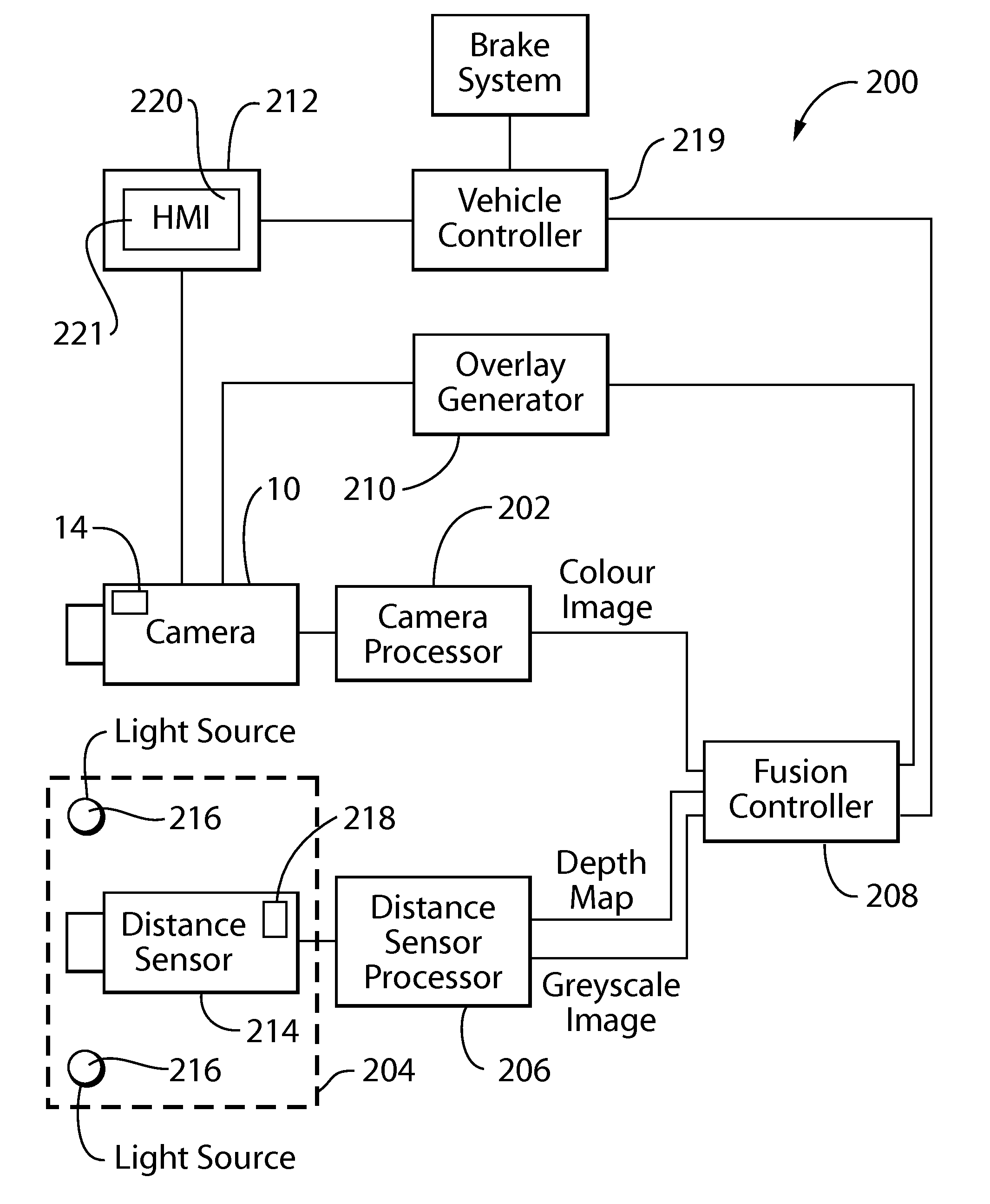
[0008]In a fifth aspect, the invention is directed to a camera system for a vehicle, including a camera, a distance sensor, and a controller that determines whether there is an element in the fields of view of the camera and the distance sensor that represents a collision risk for the vehicle based on an image from the camera and input from the distance sensor. Upon detection of an element that represents a collision risk the controller is programmed to carry out at least one action consisting of: informing the driver of the vehicle of the collision risk; and control at least one vehicle component to inhibit a collision by the vehicle with the element that represents a collision risk.
[0009]In a sixth aspect, the invention is directed to a camera system for a vehicle, including a plurality of cameras each of which is connected to a central controller by an electrical cable. Each camera has sufficient individual processing capacity to be able to modify raw i

Problems solved by technology

The typical vehicular camera, however, is relatively restricted in terms of its processing capabilities.

Method used


Image

  • Vehicular camera with on-board microcontroller
  • Vehicular camera with on-board microcontroller
  • Vehicular camera with on-board microcontroller

Examples


Embodiment Construction

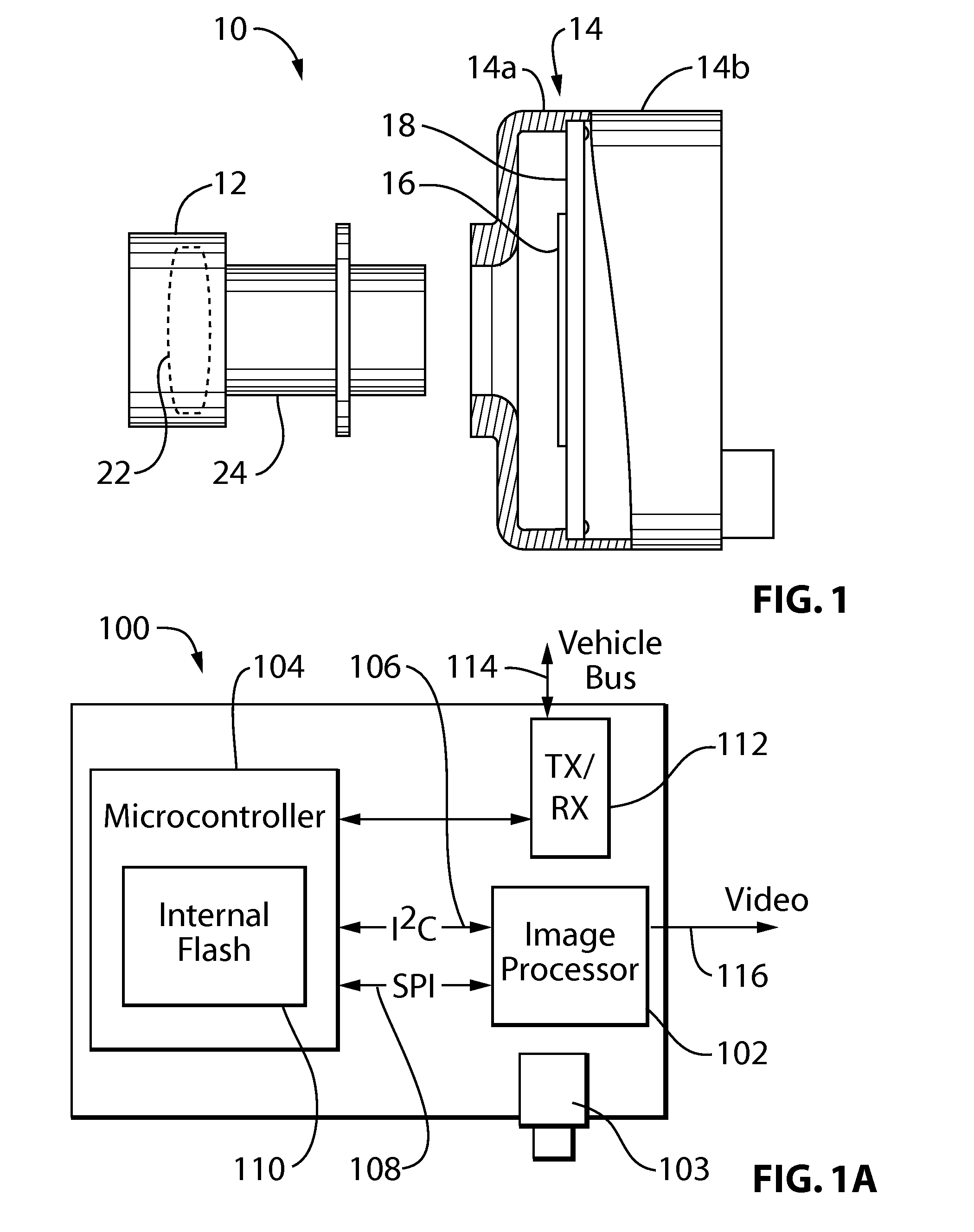
[0030]FIG. 1A is a system block diagram of a camera system 100 which includes an image processor 102 operatively connected to a camera lens 103 (as discussed in greater detail below) and a microcontroller 104. In the preferred embodiment the image processor 102 is a model MT9V126 which includes a CMOS image sensor and some control elements and is available from Aptina Imaging, San Jose, Calif., and the microcontroller 104 is a PIC microcontroller available from Microchip Technology, Chandler, Ariz., and which includes an internal flash memory 110. The image processor 102 and microcontroller 104 communicate via a serial, two wire, inter-integrated circuit (I2C) bus 106, as known in the art per se. The image processor 102 and microcontroller 104 also communicate via a four wire serial peripheral interface (SPI) bus 108, as known in the art per se. The system 100 also includes a transceiver 112 that enables the microcontroller 104 to communicate with other devices over the vehicle inte...


PUM


Abstract

In one aspect of the invention, a vehicular camera is provided, comprising a lens, a housing, an imager and a microcontroller that is capable of handling certain functions, such as applying overlays to images received by the imager, dewarping the image and / or providing different viewing modes.

Description

FIELD OF THE INVENTION[0001]The present invention relates to a camera for use in vehicles, and more particularly rearview cameras for use in vehicles.BACKGROUND OF THE INVENTION[0002]A typical camera for mounting on a vehicle has a lens member, an imaging element, a circuit board and housing members that connect together. The typical vehicular camera, however, is relatively restricted in terms of its processing capabilities.SUMMARY OF THE INVENTION[0003]In a first aspect, the invention is directed to a vehicular camera, comprising a lens, a housing, an imager and a microcontroller that is capable of handling certain functions, such as controlling the application of overlays to images received by the imager, dewarping the image and / or providing different viewing modes.[0004]In a second aspect, the invention is directed to vehicles and / or vehicular systems that incorporate the aforementioned camera. Such systems include, for example, vehicle surround view systems and object detection / ...

Claims


Application Information

Patent Timeline
IPC IPC(8): G06F7/00B60T7/12G08G1/16H04N7/18H04N7/00
CPCB60R1/00B60R2300/305G08G1/168B62D15/0295G09G2340/125G09G2380/10H04N5/23293G09G5/14H04N23/60H04N23/63H04N25/61B60W2420/403B60R2300/105B60R2300/806B60W30/09
Inventor LU, YUESHENGGIBSON, JOEL S.GEBAUER, DUANE W.SHRINER, RICHARD D.MILLER, PATRICK A.
Owner MAGNA ELECTRONICS
Learn More