
Powder Spreader

a technology of a spreader and a rotor, which is applied in the direction of additive manufacturing processes, instruments, applications, etc., can solve the problems of increasing the amount of rotors, adding up to substantial distortions in the free form of fabricated objects, and limitations of counter-rotation rollers

Active Publication Date: 2012-10-25
THE EX ONE
View PDF13 Cites 78 Cited by
  • Summary
  • Abstract
  • Description
  • Claims
  • Application Information

AI Technical Summary

Benefits of technology

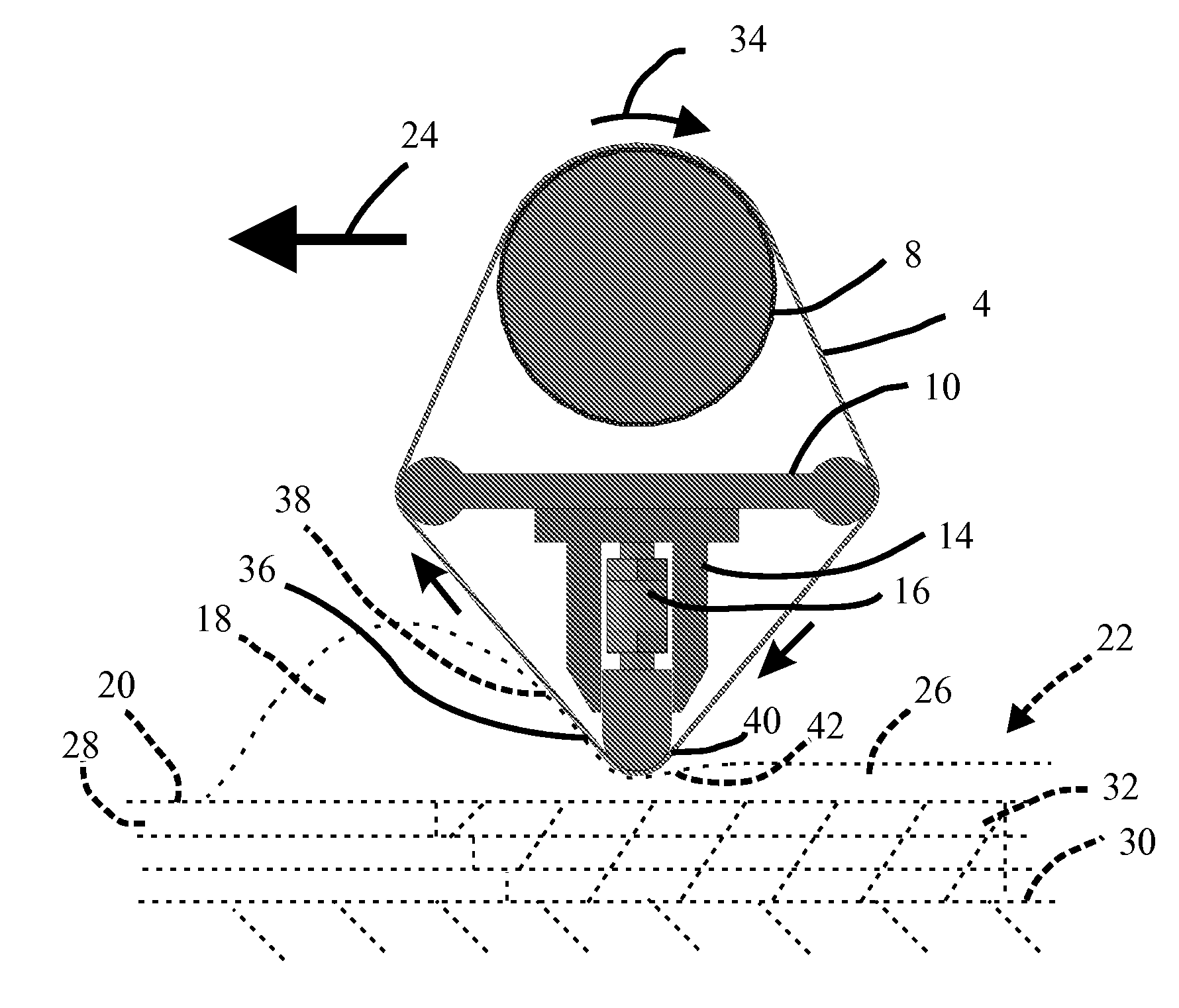
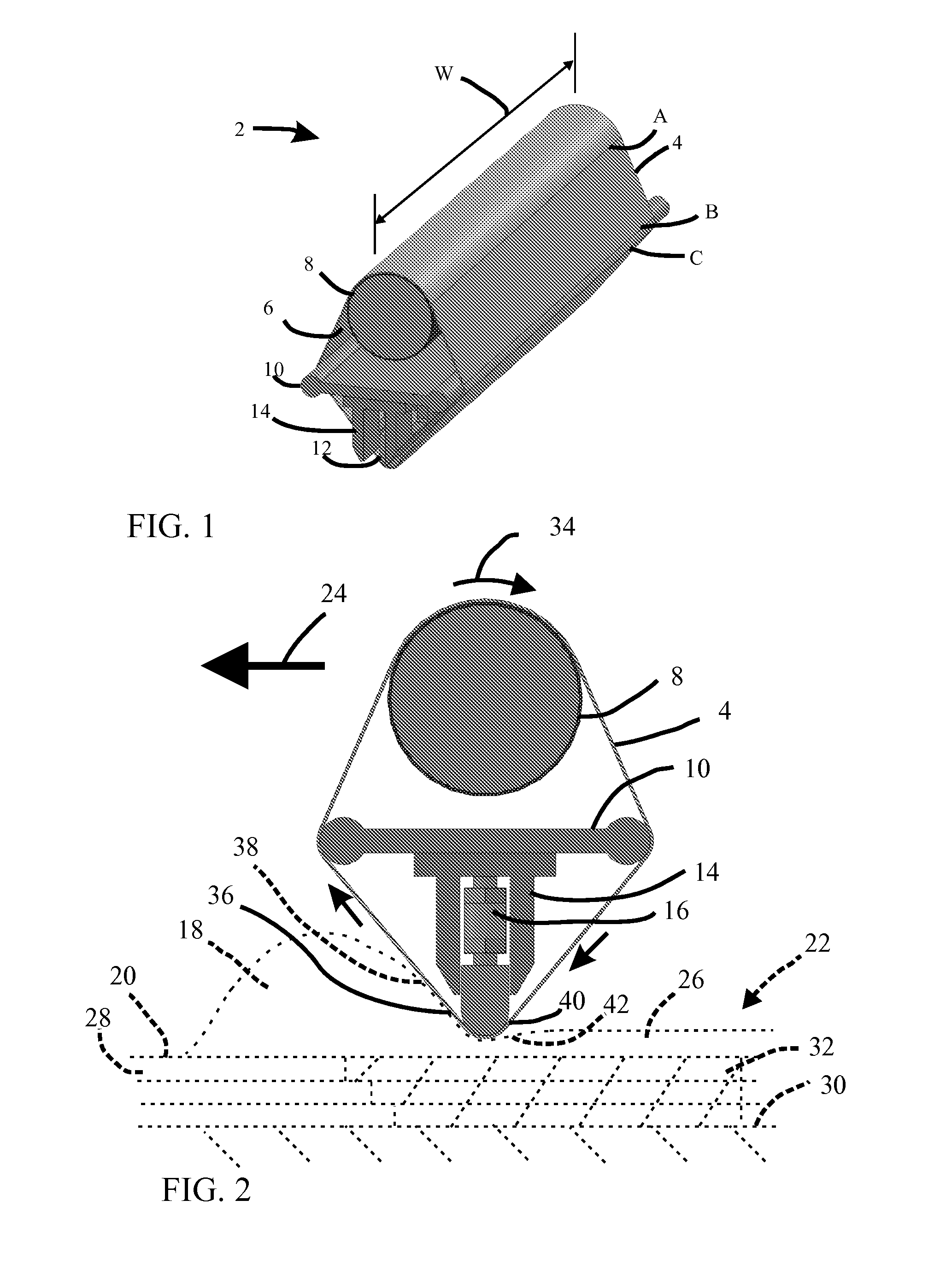
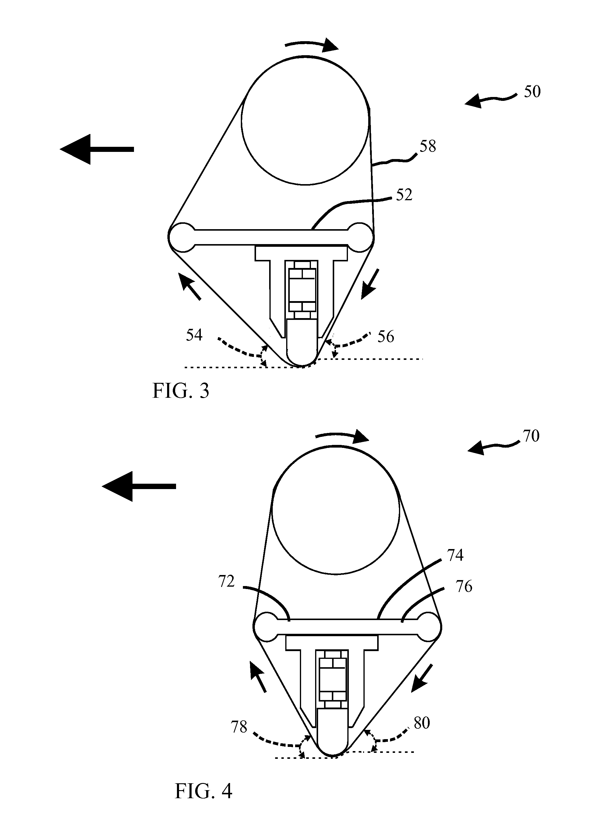
[0009]Embodiments of the present invention provide powder spreaders in which a strip of flexible material of a width which spans the powder bed is used to spread, level, and, optionally, compact deposited powder to form a layer of the powder bed. Like a counter-rotating roller, the strip surface moves relative to the deposited powder it is spreading as the working portion of the strip, i.e., the portion of the strip that is in contact with the powder, traverses across the powder bed so that it can provide lift to the powder in front of it and, optionally, compaction to the powder below it. However, unlike a counter-rotating roller, the working portion of the strip can be configured to have its leading and trailing surface contours to be different from one another, and, optionally, to have these contours and its bottom edge contour be independently adjustable.

Problems solved by technology

Even small distortions in the thickness or density uniformity of each layer can add up to substantial distortions in the free form fabricated object.
Counter-rotation rollers have their limitations.
Although short counter-rotation rollers have proven to be effective, as they become longer to accommodate larger powder beds, their small diameters tend to result in increasing amounts of wobble and flexing of the roller during use which compromises the flatness and uniformity of the powder bed.
Individual counter-rotation rollers have the further disadvantage of lacking versatility with regard to the types and sizes of powders with which they can be used.
Also, their electrical conductivities and magnetic properties are fixed and this further restricts the types and sizes of powders with which they can be optimally used inasmuch as even small electrostatic and magnetic forces can have large attractive or repulsive effects on individual powder particles.
This configuration precludes the independent control of the lift and compaction provided by the roller.

Method used


Image

  • Powder Spreader
  • Powder Spreader
  • Powder Spreader

Examples


Embodiment Construction

[0025]In this section, some preferred embodiments of the present invention are described in detail sufficient for one skilled in the art to practice the present invention. It is to be understood, however, that the fact that a limited number of preferred embodiments are described herein does not in any way limit the scope of the present invention as set forth in the appended claims.

[0026]Whenever the term “about” is used herein or in the appended claims to modify a feature of an embodiment of the present invention, it is to be construed as referring to the ordinary tolerances related to making and / or measuring the relevant feature. Whenever a range is used herein or in the appended claims to describe a feature of an embodiment of the present invention, the range is to be construed as including the stated end points of the range and every point therebetween.

[0027]For convenience of description, in FIGS. 1 through 8 and 11 through 12 there are shown schematic representations of powder ...


PUM

PropertyMeasurementUnit
Angleaaaaaaaaaa
Flexibilityaaaaaaaaaa
Shapeaaaaaaaaaa

Abstract

Powder spreaders suitable for use with layered manufacturing processes are disclosed in which a strip of flexible material of a width which spans the powder bed is used to spread, level, and, optionally, compact deposited powder to form a layer of the powder bed. The strip surface moves relative to the deposited powder it is spreading as the working portion of the strip, i.e., the portion of the strip that is in contact with the powder, traverses across the powder bed so that it can provide lift to the powder in front of it and, optionally, compaction to the powder below it. The working portion of the strip can be configured to have its leading and trailing surface contours to be different from one another, and, optionally, to have these contours and its bottom edge contour be independently adjustable. Layered manufacturing systems comprising such powder spreaders are also disclosed.

Description

FIELD OF THE INVENTION[0001]The present invention relates to an apparatus for spreading powder uniformly across a surface to initiate or add to a powder bed, especially a powder bed suitable for a layered manufacturing process.BACKGROUND OF THE INVENTION[0002]Powder spreaders play an important role in the initiation and creation of powder beds that are used in layered manufacturing processes known as free form fabrication processes. In free form fabrication processes, the powder bed is formed layer by layer upon a support surface. Typically, the thickness of the powder layer is about the same as the average powder particle thickness of the powder which is being spread or a multiple thereof. Confining walls are supplied beforehand or constructed in situ as the process proceeds to retain the powder layers in place to form the bed. After a powder layer is spread, powder particles in selected portions of the powder layer may be bonded together and / or to an underlying layer through the s...

Claims


Application Information

Patent Timeline
IPC IPC(8): B05C1/00B05C11/00
CPCB29C67/0081B05C11/026B29C64/165B33Y30/00
Inventor BRUNERMER, DAN
Owner THE EX ONE
Learn More