Room vent humidifier

a technology of humidifier and room vent, which is applied in the direction of heating types, gas purification by liquid washing, fuel gas production, etc., can solve the problems of not being able to solve the problem in its entirety, reducing the moisture level, and not being able to completely bring the humidity level, so as to prevent overflow and keep the water level low

Inactive Publication Date: 2012-10-25
RODRIGS JERI
View PDF2 Cites 17 Cited by
  • Summary
  • Abstract
  • Description
  • Claims
  • Application Information

AI Technical Summary

Benefits of technology

[0049]The evaporative filter element may be made of standard absorbent humidifier evaporative wick filter material with porous cell holes in a honey comb formation, and may stand vertically in the lower water pan, in the path of the air flow. The evaporative filter element may have a plastic frame for rigidity. It also may have a sheet metal mesh on the air outlet side to withstand the air flow without warping.
[0051]A protective grill may be installed at the air exit of the casing to protect the evaporative filter element from any external damage and to prevent any foreign debris entering the humidifier. The grill may have a slide shutter at the inside side of the grill which may be closed to control the air flow.
[0052]The pin hole openings at the bottom of the water tank and right above the evaporative filter element pass low amounts of water to moisten the evaporative filter element. The hot air from the heat source and the vent is directed through the main air passage corridor of the humidifier and passes through the moisture filled evaporative filter element which is at the hot air exit causing the air to become moist and humidify the surroundings.
[0053]The humidity level of the surroundings of this room vent humidifier is naturally and automatically controlled by the ON and OFF cycle of air flow from the heat source. The same on / off cycle keeps the water level in the lower water pan at a certain level and prevents it from overflowing. While the heat source is in the OFF mode, the evaporation rate from the filter element will be low. This will allow more water to drip into the lower water pan which will accumulate water. On the other hand, while the heat source is in the ON mode the evaporation rate of the filter element will be high, thus consuming all the water dripping from the main water tank and in the water pan. That ON mode high consumption of water from the water pan will keep the water level low and prevent over-flow.
[0056]The main water tank, evaporative filter element, the grill and the lower water pan are easily detachable with a tab click type of detent mechanism making maintenance and cleaning of each component efficient. The click or detent assembly mechanism of all the modular parts without any screws is one of the main advantages of embodiments of this invention. Moreover, for seasons where humidification of the air is not required, the humidifier can simply be lifted from the vent and put into storage and replaced with a passive vent cover.

Problems solved by technology

Electrically powered furnace humidifiers are available but they are not entirely effective in bringing the humidity level to a comfortable level because furnace humidifiers are installed close to the heat source which makes them ineffective especially in a multiple story building; by the time heated air reaches the farthest level of the building the moisture level is reduced.
A central humidifier cannot solve the problem in its entirety.
Most modern day room humidifiers now on the market are electrically powered and must be plugged into a wall socket to operate, so there is cost involved in operating them.
These electrically powered humidifiers have electrical motors therein which may emit an unpleasant noise.
Because they contain complicated electrical devices inside, they are prone to breakdowns.
However, these humidifiers are usually designed to be used with one type of heating system (often radiators) and are not very versatile.
Many of these prior art humidifiers tend to be cumbersome since they are bulky and take up a lot of space on the floor and may interfere with normal human activity in the room.
They may also not be compatible for fixing onto the modern day forced air furnace vents.
Also, because the water container in them is usually placed between the heat source and the absorbent material, these humidifiers are not very effective or efficient.
Previously-known such humidifiers, including the ones mentioned below, may have one or more of the following drawbacks: A) their main water tanks are not detachable from the casings and portability of main water tank for refills becomes an issue; this makes refilling of the tank difficult and not practical for commercial market applications; and B) they have small tank capacity and need frequent refills; C) They are not a modular in design for easy manufacture or easily attachable to vents; D) The evaporative element is not stand alone and usually sits directly in the main water tank and evaporates directly from the main water tank, making it inefficient and difficult to maintain.
This means that the water tank is small, and may be awkward to fill.
The humidifier disclosed in U.S. Pat. No. 7,828,275 to Won has the following drawbacks: a plurality of evaporating filters makes the humidifier costly to manufacture and also hard to maintain and also makes it costly to replace the evaporating elements.
The many evaporating filters also make the evaporation rate high, relative to the reservoir size, which would require frequent re-fillings of the water tank.
A paper towel is not an efficient and a rigid evaporating medium to humidify and to withstand the rough usage experienced in typical households.
In this application the paper towel is partly exposed which makes it liable to damage, so this would need frequent replacement.
The humidifier can only be used with a floor register and cannot be used with a wall register or vent.
The humidifier described in U.S. Pat. No. 5,403,233 to Daneshvar is a rather fragile looking device used partly for decoration; the water trough is shallow and could not be expected to transmit much moisture to the evaporating elements.
The humidifier disclosed in U.S. Pat. No. 5,324,230 to Hist is a humidifier with an evaporating element which is exposed openly and not inside the casing, making it fragile.
The main water tank is of low capacity and needs frequent refills for normal operation.
The water tank is also open and exposed to the room and may be hazardous to kids and pets.
It has a complicated installation mechanism for attachment to a wall.
It also has the problem that the main water tank does not detach from the casing and so is not portable for refills.
This makes refilling the tank difficult and not practical for commercial market applications.
The humidifier disclosed in U.S. Pat. No. 4,327,630 to Brassine is too complicated, and has too many intricate fittings, to provide a marketable product.
The humidifier disclosed in U.S. Pat. No. 4,240,991 to Shaub has a humidifier with a rotating propeller, which may not work well with the draft provided by a forced air furnace, and could create a blockage to air flow.
This also can only be used with wall register, and cannot be used with a floor register or vent.
Its water tank is of low capacity and needs frequent refills.
The insert material is bulky and can cause large mineral deposits from the water.
The apparatus appears to be heavy and probably will not hang properly when the reservoir is filled with full capacity.
The apparatus has parts which need to be fitted both above and below the register, which would make installation awkward.
Though the humidifiers of the type described above have been designed for humidifying heated air being forced into individual rooms, they seem to have met with minimal success in the commercial market due to lack of simplicity, lack of cost effectiveness, being hard to maintain, and not easy to install.
Some have complex parts not designed to be mass produced at low cost, as is required for such apparatus to be employed in multiple rooms in a household.

Method used


Image

  • Room vent humidifier
  • Room vent humidifier
  • Room vent humidifier

Examples


embodiment 1

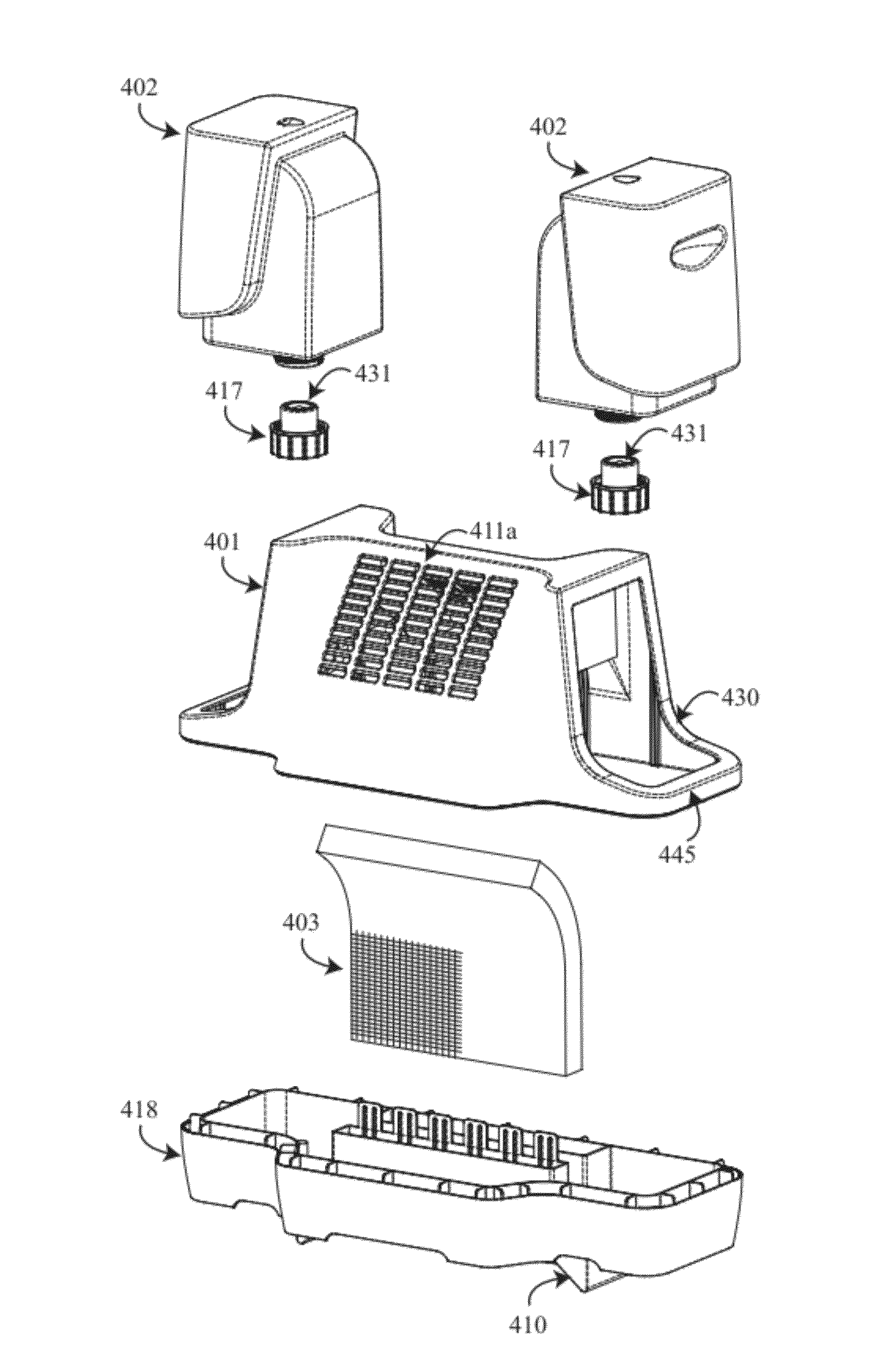
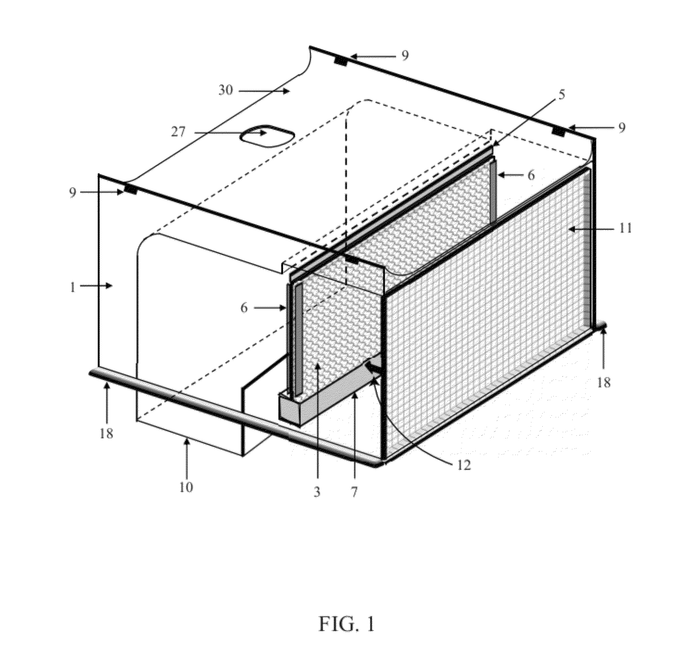
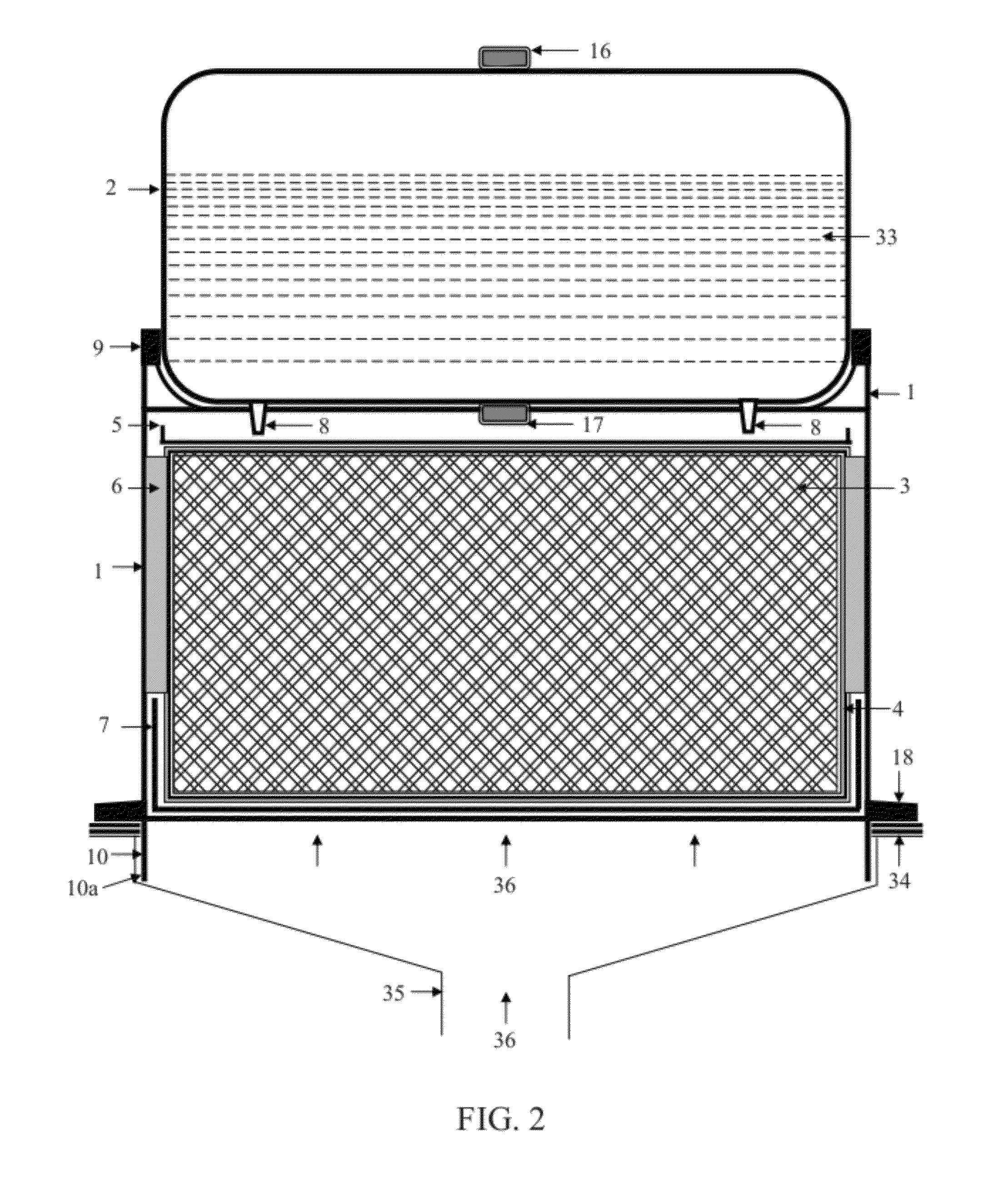
[0081]Preferred Embodiment 1 of this invention is illustrated in FIGS. 1-3 and 5-10. In this embodiment, the room humidifier is comprised mainly of casing (1), main water tank (2), evaporative filter element (3), lower water pan (7), and air outlet grill (11). Main water tank (2) and evaporative filter element (3) are located within casing (1) with evaporative filter element (3) being located underneath main water tank (2). Evaporative filter element (3) stands vertically inside the water pan (7) which surrounds a lower edge portion of the filter element. All of the components of this embodiment, including casing (1) and main water tank (2), can be made of plastic for the exception of evaporative filter element (3).

[0082]Casing (1) is the main body of the room vent humidifier on the top of which the main water tank (2) is situated. Casing (1) has projecting tabs on top providing water tank click tabs (9) for the main water tank (2) to slide and click in place.

[0083]The bottom of the...

embodiment 2

[0095]As illustrated in FIG. 4, the humidifier of this Embodiment 2 can be fixed onto a wall vent opening. In this installation, air inlet base (110) is attached to the room wall (37) instead of room floor vent (34) to direct the air flow (36) to evaporative filter element (3). The air corridor is a horizontal straight hollow opening and does not have any air deflector. The casing (101) is fixed on to the room wall (37) with the help of fixing screws (38). The components, installation and operation of the unit remain same as the preferred embodiment except for the above explained differences.

[0096]Optional embodiment of main water tank (102):

[0097]FIG. 9 illustrates an optional main water tank (102) that can be employed within certain embodiments of this invention including the first embodiment. Two major differences in this optional main water tank (102) from main water tank (2) of the first embodiment are:

[0098]1) Use of a float valve assembly (21) to fill the water tank (102) and...

embodiment 3

[0104 of this invention is designed to give air flow in line with the standards of some countries. The main difference of this embodiment compared to the previous embodiments is the way hot air comes out of the humidifier. In this embodiment, hot air is coming out of two sides of the apparatus instead of the front as in the preferred embodiment.

[0105]FIG. 11 and FIG. 12 show respectively a sectionalized front view of this embodiment, and a top plan view of the casing (201) without main water tank (202). The main purpose of this embodiment is to direct air flow through the sides of the humidifier and to the sides of the room rather than only through the front of the humidifier.

[0106]In Embodiment 3, many of the components of the invention remain the same as the preferred embodiment explained above and used in the exact same context; however the following components are duplicated:[0107]Evaporative filter element (3)[0108]Evaporative filter element frame distribution trough (5)[0109]L...


PUM

PropertyMeasurementUnit
transparentaaaaaaaaaa
rigidityaaaaaaaaaa
lengthaaaaaaaaaa

Abstract

A room humidifying apparatus is provided which operates with minimum cost and without any electrical power. The humidifier is located so as to make use of a stream of air coming from a register. The humidifier has a casing carrying a main water tank, a water pan and an evaporative filter element which are located in the casing. The tank drips water onto the filter element, which has a lower portion located in the water pan to collect any excess water dripping down the filter element and also to moisten it with capillary effect. Heated air from the register becomes humidified on passing through the filter element. The water tank can be filled manually from the top or be detachable and filled through a bottom refill opening. Alternatively, the water tank can be connected to a water source with a valve to regulate the flow of water into the water tank. The water tank may be balanced so as to displace, for example tilt, from a first position when it contains water to a second position when it is empty.

Description

CROSS-REFERENCE TO RELATED APPLICATIONS[0001]This application is related to and claims priority from U.S. Provisional patent application No. 61 / 478,546 filed Apr. 24, 2011 and Canadian patent application No. 2,738,326 filed Apr. 26, 2011, the entire contents of each of which are incorporated herein by reference.TECHNICAL FIELD[0002]This invention relates to a type of room humidifier which does not need an external source of power (i.e. electricity), and which can operate at a low cost.BACKGROUND ART[0003]Interior air can become very dry in the countries like Canada, Europe and Northern US during the winter months where forced air furnace heating systems are provided in many homes. The interior relative humidity level can drop to as low as 15% if the house is not equipped with a humidifier. Electrically powered furnace humidifiers are available but they are not entirely effective in bringing the humidity level to a comfortable level because furnace humidifiers are installed close to ...

Claims


Application Information

Patent Timeline
Patent Type & Authority Applications(United States)
IPC IPC(8): F24F3/14B01F3/04
CPCF24F2006/008F24F6/04
Inventor RODRIGS, JERIHENDERSON, JAMESBAILEY, KEVIN J.
Owner RODRIGS JERI
Why Eureka
Try Eureka